Air Conditioner Compressor Replacement
TM 9-2320-363-34-1 · Chapter 11.1 — Air Conditioning System Maintenance
This Task Covers:      a. Removal b. Installation

Applicable Configuration:                              Equipment Condition:

All except M915A2 and M916A1                           Reference              Condition Description

Tools and Special Equipment:                           TM 9-2320-363-20       Batteries Disconnected
                                                       TM9-2320-363-20        Alternator Belt Removed
Tool Kit, SC 5180-90-CL-N26                            Page 11.1-2            Refrigerant Recovered
Shop Equipment, SC 4910-95CL-A31
                                                       General Safety Instructions:
Materials/Parts:

Nut, Lock (2)          P/N 210980 010010                                WARNING
Washer, Lock (6)       P/N 23-09318-011
Packing, Preformed     P/N 011C944-70                        Use care to prevent refrigerant from
Packing, Preformed     P/N 015C944-70                        touching your skin or eyes, because liquid
Receiver-Drier         P/N 088335-00                         refrigerant, when exposed to air, quickly
Cap and Plug Set       Appendix B, Item 7.1                  evaporates and will freeze skin or eye
Loctite                Appendix B, Item 33                   tissue. Serious injury or blindness could
Oil, Refrigerant       Appendix B, Item 43.1                 result if you come in contact with liquid
Tags, Identification   Appendix B, Item 55                   refrigerant.

References:                                                  Refrigerant R-134a air conditioning
                                                             systems should not be pressure tested or
TM 9-2320-363-10                                             leak tested with compressed air.
TM 9-2320-363-20                                             Combustible mixtures of air and R-134a
                                                             may form, resulting in a fire or explosion,
                                                             which could cause personal injury.

                                                NOTE

       If the air conditioner compressor is being removed as an equipment condition for engine
       replacement, DO NOT disconnect refrigerant hoses and fittings and only perform the
       following four steps.

               Disconnect compressor clutch electrical lead.
               Cut cable ties securing refrigerant hoses.
               Remove compressor mounting bolts.
               Move compressor from mounting bracket to truck frame and secure in place
               to prevent damage.
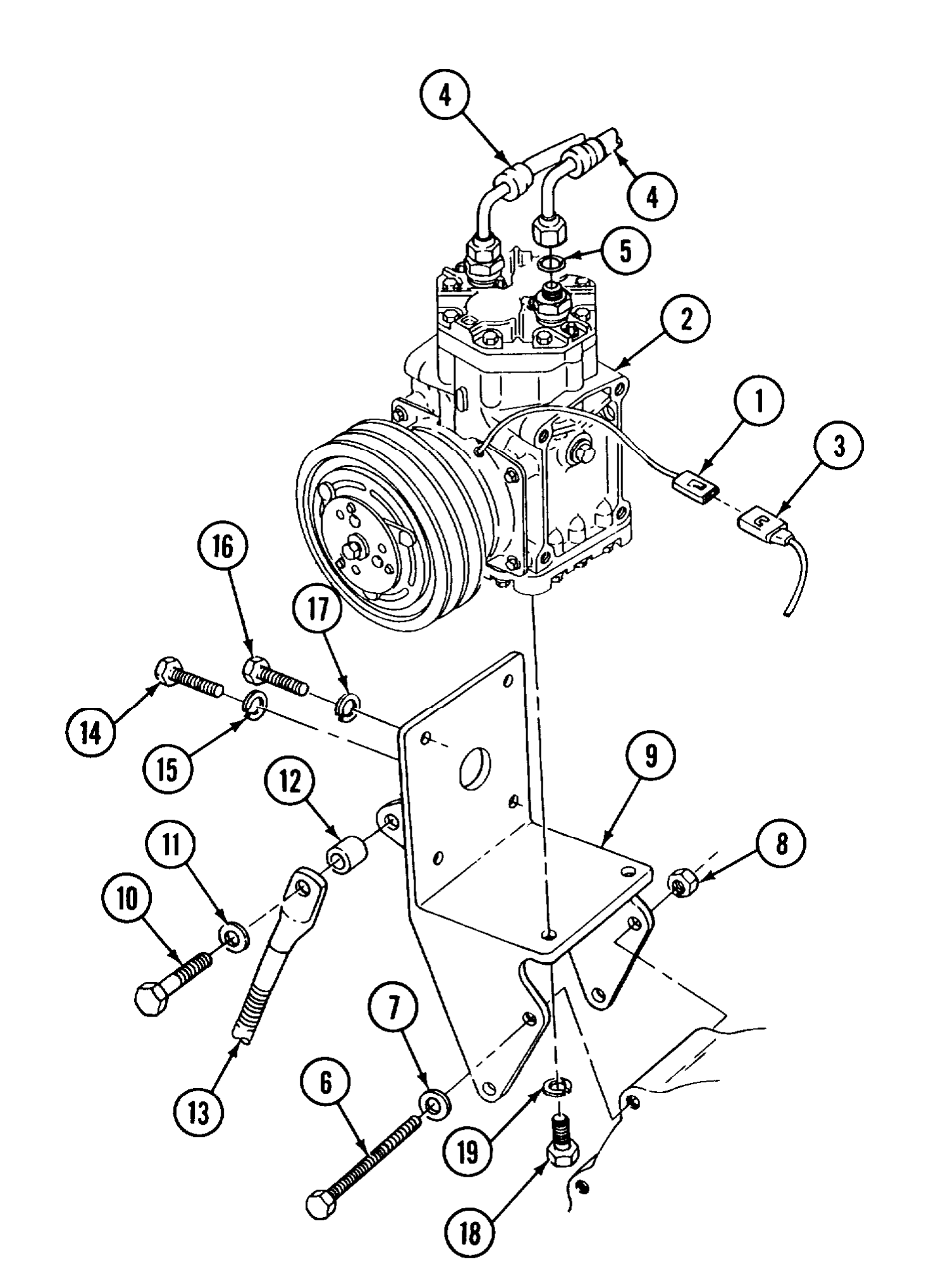
1. DISCONNECT CONNECTOR (1) OF COMPRESSOR (2) FROM CONNECTOR (3).
Do not disconnect or connect refrigerant fittings using only one wrench. Hold one fitting in place using a wrench, and turn the other fitting with a second wrench.
2. TAG AND DISCONNECT TWO HOSES (4) FROM TOP OF COMPRESSOR (2). INSTALL PLUGS IN LINES AND DISCARD PREFORMED PACKING (5).
3. REMOVE TWO SCREWS (6) WASHERS (7) LOCK NUTS (8) AND COMPRESSOR (2) WITH BRACKET (9) ATTACHED. DISCARD LOCK NUTS.
4. SECURE BRACKET (9) IN SOFT JAWED VISE.
5. REMOVE SCREW (10), WASHER (11) AND SPACER (12) FROM ALTERNATOR ADJUSTMENT BOLT (13).
6. REMOVE SCREW (14) AND LOCK WASHER (15) FROM SIDE OF COMPRESSOR BRACKET (9). DISCARD LOCK WASHER.
7. REMOVE THREE SCREWS (16) AND LOCK WASHERS (17) FROM SIDE OF COMPRESSOR BRACKET (9). DISCARD LOCK WASHERS.
8. REMOVE TWO SCREWS (18) AND LOCK WASHERS (19) FROM UNDERSIDE OF COMPRESSOR BRACKET (9).
9. REMOVE COMPRESSOR (2) FROM BRACKET (9).
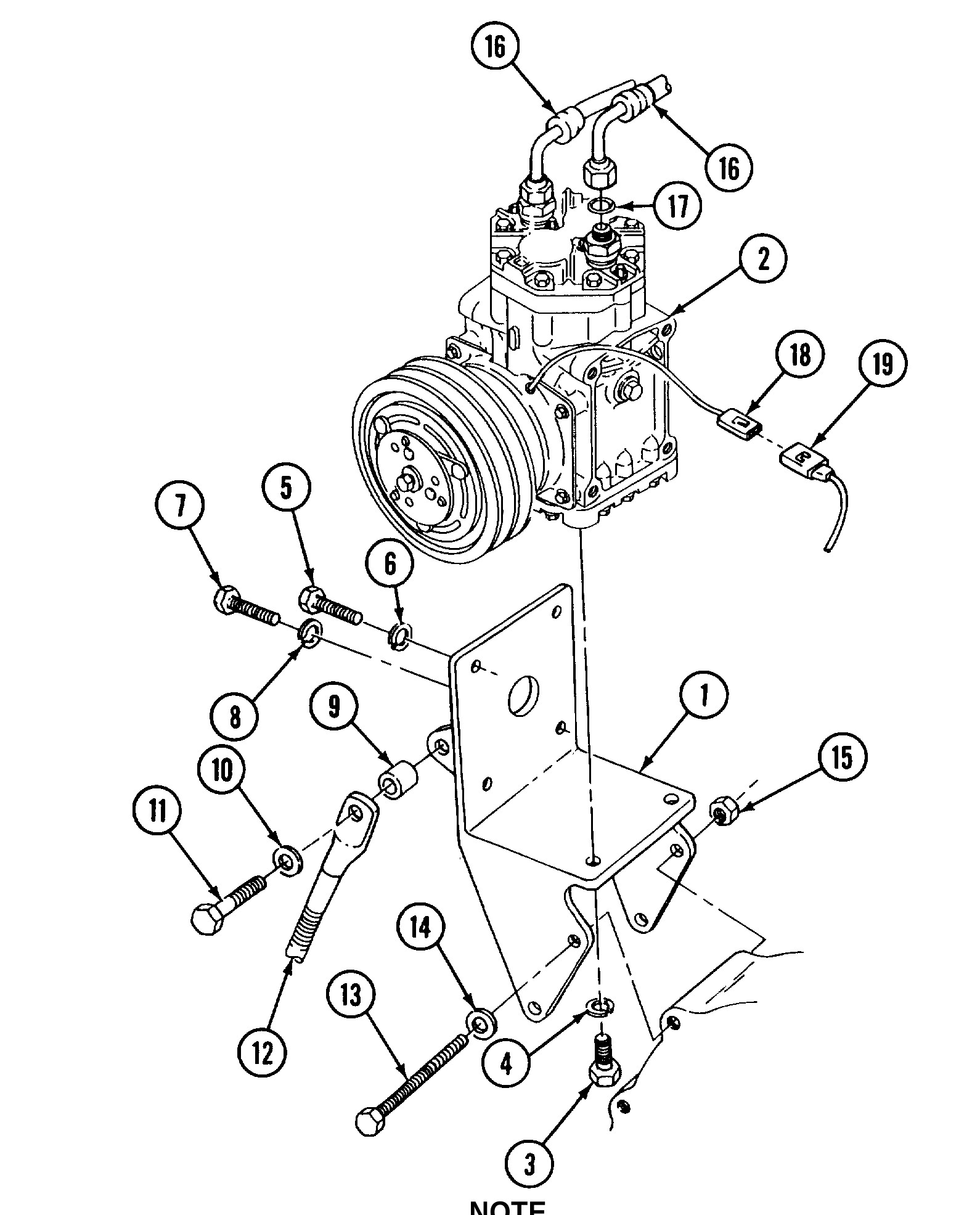
1. WITH BRACKET (1) SECURED IN SOFT JAWED VISE, POSITION COMPRESSOR (2) ONTO BRACKET (1) AND ALIGN UNDERSIDE MOUNTING HOLES ON COMPRESSOR WITH MOUNTING HOLES ON BRACKET.
2. INSTALL TWO SCREWS (3) AND NEW LOCK WASHERS (4). HAND TIGHTEN.
3. ON SIDE Of BRACKET (1), INSTALL THREE SCREWS (5) AND NEW LOCK WASHERS (6). HAND TIGHTEN.
4. ON SIDE OF BRACKET (1) INSTALL SCREW (7) AND NEW LOCK WASHER (8). HAND TIGHTEN. --
5. INSTALL SPACER (9) WASHER (IO), AND SCREW (11) TO ALTERNATOR ADJUSTMENT BOLT (12).
6. TORQUE UNDERSIDE SCREWS (3) TO 20-25 LB-FT(27-34 N.m).
7. TORQUE SIDE MOUNTING SCREWS (5 AND 7) TO 20-25 LB-FT (27-34 N.m).
8. POSITION BRACKET (1) WITH COMPRESSOR (2) ONTO ENGINE BLOCK AND INSTALL TWO SCREWS (13), NEW LOCK WASHERS (14) AND NEW LOCK NUTS (15).
9. CONNECT TWO HOSES (16) TO TOP OF COMPRESSOR (2) USING NEW PREFORMED PACKINGS (17) COATED WITH REFRIGERANT OIL AND LOCTITE APPLIED TO MALE FITTINGS.
10. CONNECT CONNECTOR (18) OF COMPRESSOR (2) TO CONNECTOR (19).
11. REPLACE RECEIVER-DRIER (page 11.11-14).
12. SERVICE AIR CONDITIONER COMPRESSOR (page 11.1-23).
Install and adjust alternator belt (TM 9-2320-363-20). Charge and leak test air conditioning system (page 11.1-2 and TM 9-2320-363-20). Connect batteries (TM 9-2320-363-20). Check operation of air conditioning system (TM 9-2320-363-10).