Front Axle Caster Adjustment
TM 9-2320-363-34-1 · Chapter 5 — Front Axle Maintenance
This task covers: Adjustment
Applicable Configuration:                         General Safety Instructions:
M915A2
                                                                   WARNING
Tools and Special Equipment:                                Before removing shim(s),
Shop Equipment, SC 4910-95-CL-A31                          make sure vehicle is properly
Tool Kit, SC 5180-90-CL-N05                                supported to prevent possible
                                                           injury to personnel.
Materials/Parts:
                                                            If more than one shim is to
Compound,                   Appendix B, Item 11            be added, shims must be
Antiseize                                                  welded together prior to
                                                           installation. Failure to do so
                                                           may cause shim slippage
                                                           resulting      in   equipment
                                                           damage and/or injury to
                                                           personnel.
Manufacturer’s operating instructions for alinement equipment must be followed to perform step 1.
1. MEASURE CASTER ANGLE. ANGLE MUSTBE +3-1/2° TO +6-1/2°.
2. REMOVE FOUR NUTS (1) AND FOUR WASHERS (2) FROM TWO U-BOLTS (3).
3. RAISE SPRING (4) HIGH ENOUGH FROM AXLE (5) TO ALLOW REMOVAL OF SHIM(S) (6).
4. REMOVE SPACER (7), SHIM(S) (6), AND DOWEL (8).
5. INSTALL DOWEL (8) IN AXLE (5).
6. INSTALL NEW SHIM(S) (6) TO OBTAIN +3-1/2° TO +6-1/2° OF CASTER ANGLE.
Make sure dowel protrudes thru shim(s) enough to hold spacer in place. if dowel will not protrude into spacer, replace dowel.
7. INSTALL SPACER (7).
8. LOWER SPRING (4) ONTO AXLE (5).
9. COAT THREADS OF TWO U-BOLTS (3) WITH ANTISEIZE COMPOUND.
10. INSTALL FOUR WASHERS (2) AND FOUR NUTS (1) ON TWO U-BOLTS (3). TIGHTEN NUTS TO 380-460 LB-FT (515-624 N.m).
5-61/(5-62 Blank)
This chapter illustrates and describes procedures for maintenance of the rear axle and related parts. A list of tasks contained in this chapter is shown below.
Page
Forward-Rear Axle Differential Carrier Replacement 6-2
Output Shaft Replacement and Repair 6-7
Rear-Rear Axle Differential Carrier Replacement 6-12
Rear Axle Replacement (M915A2) 6-16
Rear Axle Replacement (All Except M915A2)) 6-22
Rear Yoke and Oil Seal Replacement (M915A2) 6-28
Rear Yoke and Oil Seal Replacement (All Except M915A2)) 6-30
FORWARD-REAR AXLE DIFFERENTIAL CARRIER REPLACEMENT This task covers: a. Removal b. Cleaning c. Inspection d. Installation
                                                      General Safety Instructions:

Tools and Special Equipment:                                             WARNING
Shop Equipment, SC 4910-95-CL-A31                            l     Forward-rear  axle  differential
Tool Kit, SC 5180-90-CL-N05                                      carrier weighs 1,160 lb (526
                                                                 kg). Attach suitable floor jack
Materials/Parts:                                                 prior to removal or installation
Compound, Sealing         Appendix B, Item 16                    to prevent possible injury to
                                                                 personnel.
Personnel Required: (2)
                                                             l      Adhesives,  solvents,  and
References:                                                      sealing compounds can burn
                                                                 easily, can give off harmful
TM 9-2320-363-20                                                 vapors, and are harmful to
                                                                 skin and clothing. To avoid
                                                                 injury or death, keep away
Equipment Condition:
                                                                 from open fire and use in
Reference                  Condition Description                 well-ventilated     area. If
                                                                 adhesive, solvent, or sealing
TM 9-2320-363-20           Air System Drained                    compound gets on skin or
                                                                 clothing, wash immediately
TM 9-2320-363-20           Axle Shafts Removed
                                                                 with soap and water.
TM 9-2320-363-20           Grate Removed
                           (M916A1 and M916A2
TM 9-2320-363-20           Drivelines Disconnected
TM 9-2320-363-20           Axle Oil Filter Removed

Page 6-7                   Output Shaft Removed
TM 9-2320-363-20           Axle Oil Drained
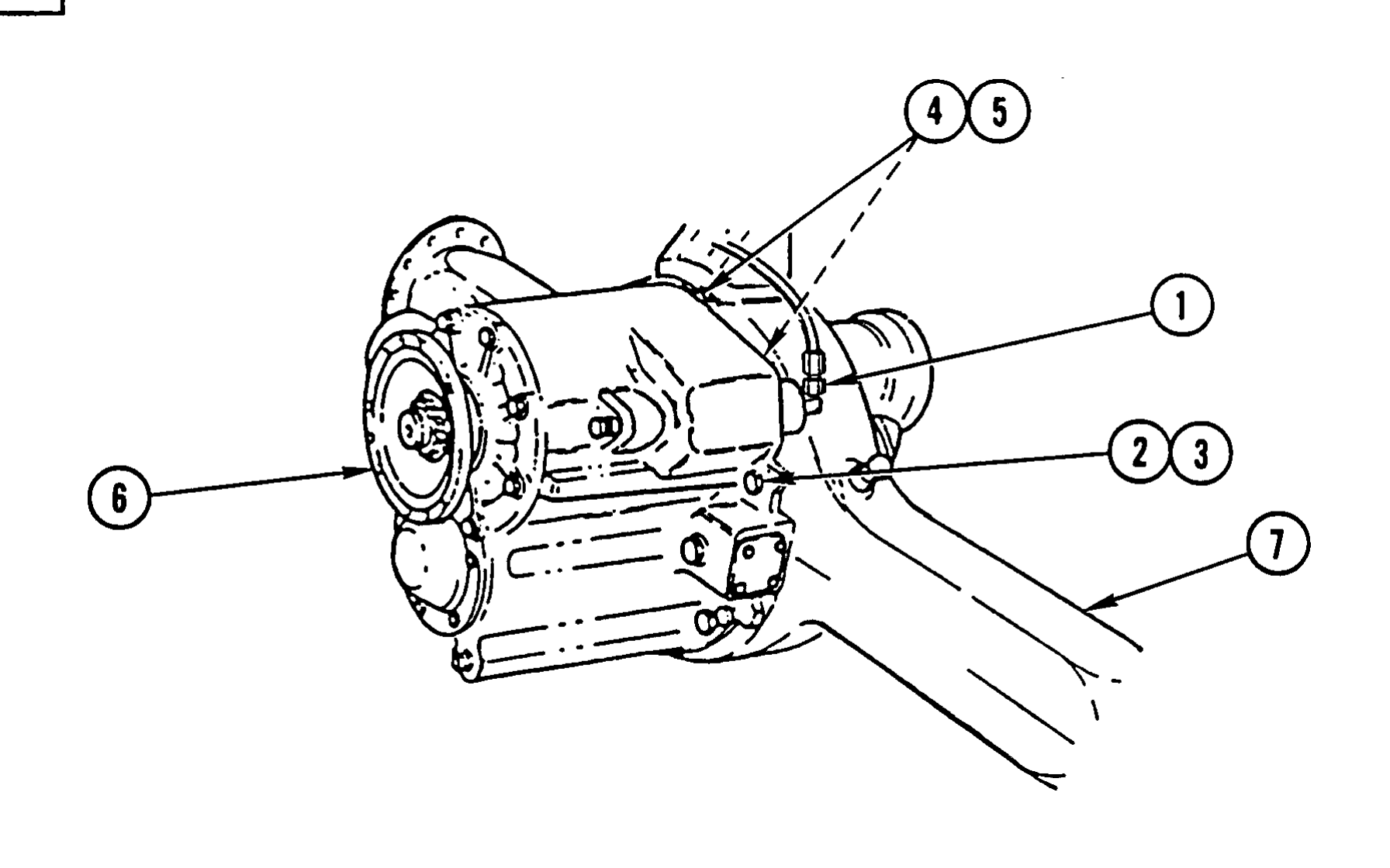
1. DISCONNECT AIR LINE (1).
Forward-rear axle differential carrier weighs 1,160 lb (526 kg). Attach suitable floor jack prior to removal to prevent possible injury to personnel.
If axle assembly has been removed from vehicle, perform steps 2 and 3 only.
2. REMOVE 10 CAPSCREWS (2), 10 WASHERS (3), 2 NUTS (4), AND 2 WASHERS (5).
3. LOOSEN DIFFERENTIAL CARRIER (6) BY TAPPING AROUND FLANGE.
4. REMOVE DIFFERENTIAL CARRIER (6) FROM AXLE (7) AND LOWER DIFFERENTIAL CARRIER (6) ONTO FLOOR JACK. ROLL DIFFERENTIAL CARRIER (6) FROM UNDER VEHICLE.