2-32. Fuel Injection Pump Repair
TM 9-2815-237-34 · Chapter 2 — Engine Maintenance
This task covers:
a. Disassembly c. Inspection
b. Cleaning d. Assembly
INITIAL SETUP:
Tools                                                    Material/Parts
 General mechanic’s tool kit:                             Overhaul kit (Appendix D, Item 27)
   automotive (Appendix E, Item 1)                        Seven lockwashers (Appendix D, Item 25)
Special Tools                                             Two locknuts (Appendix D, Item 24)
                                                          Adjusting plug (Appendix D, Item 35)
 Hex head driver, 5/32-in. (Appendix E, Item 54)          Valve stop (Appendix D, Item 53)
 Hex head driver, 1/8-in. (Appendix E, Item 55)           Cap (Appendix D, Item 4)
 Hex head driver, 5/16-in. (Appendix E, Item 9)           Calibrating fluid (Appendix B, Item 4)
 Hex head driver, 1/4-in. (Appendix E, Item 56)           Seal lubricant (Appendix, B Item 12)
 Torx drive (Appendix E, Item 42)                         Sealing compound (Appendix B, Item 18)
 End cap wrench (Appendix E, Item 44)                     Lacquer thinner (Appendix B, Item 20)
 Holding fixture (Appendix E, Item 46)                     or Acetone (Appendix B, Item 2)
 Governor weight support (Appendix E, Item 43)
 Drive shaft bearing installer                           Manual References
   (Appendix E, Item 39)                                  TM 9-2815-237-34P
 Drive shaft seal installer (Appendix E, Item 40)         TM 9-2320-280-20
 Roller-to-roller setting tool                           Equipment Condition
   (Appendix E, Item 45)
 Throttle and shutoff shaft bushing                       Remove fuel injector pump (para. 2-15).
   (Appendix E, Item 41)                                 General Safety Instructions
 Pilot tube mandrel (Appendix E, Item 47)                 • Wear eyeshields when using compressed air.
 Delivery valve extractor (Appendix E, Item 48)           • Do not allow solvents to get on skin or clothing.
                                                          • Compressed air for cleaning purpose will not
                                                            exceed 30 psi (207 kPa).

                                                 NOTE
                • The fuel injection pump repair procedures for pre-1990, 1990 and
                  above 6.2L and 6.5L engines are basically the same. Difference in
                  procedures are noted. Refer to para. 1-10 to determine engine model
                  before ordering replacement parts.
                • Before disassembly, fuel injection pump should be tested
                  (para. 2-33.c, 2-34.c, or 2-35.c) on calibration stand to determine
                  type of pump malfunction.
                • Do not disassemble fuel injection pump if no malfunction is found
                  after preliminary test.
                • Work area should be clean, well-ventilated, and free from blowing
                  dirt and dust.
a. Disassembly
1. Clean exterior of fuel injection pump (9) in accordance with para. 2-9.
2. Mount pump (9) in holding fixture and secure fixture in vise.
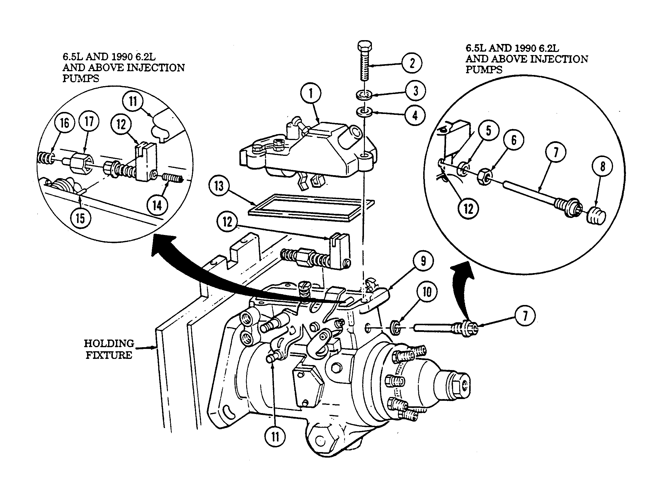
3. Remove three screws (2), lockwashers (3), and washers (4) from governor control cover (1). Discard lockwashers (3).
4. Remove cover (1) and gasket (13). Discard gasket (13).
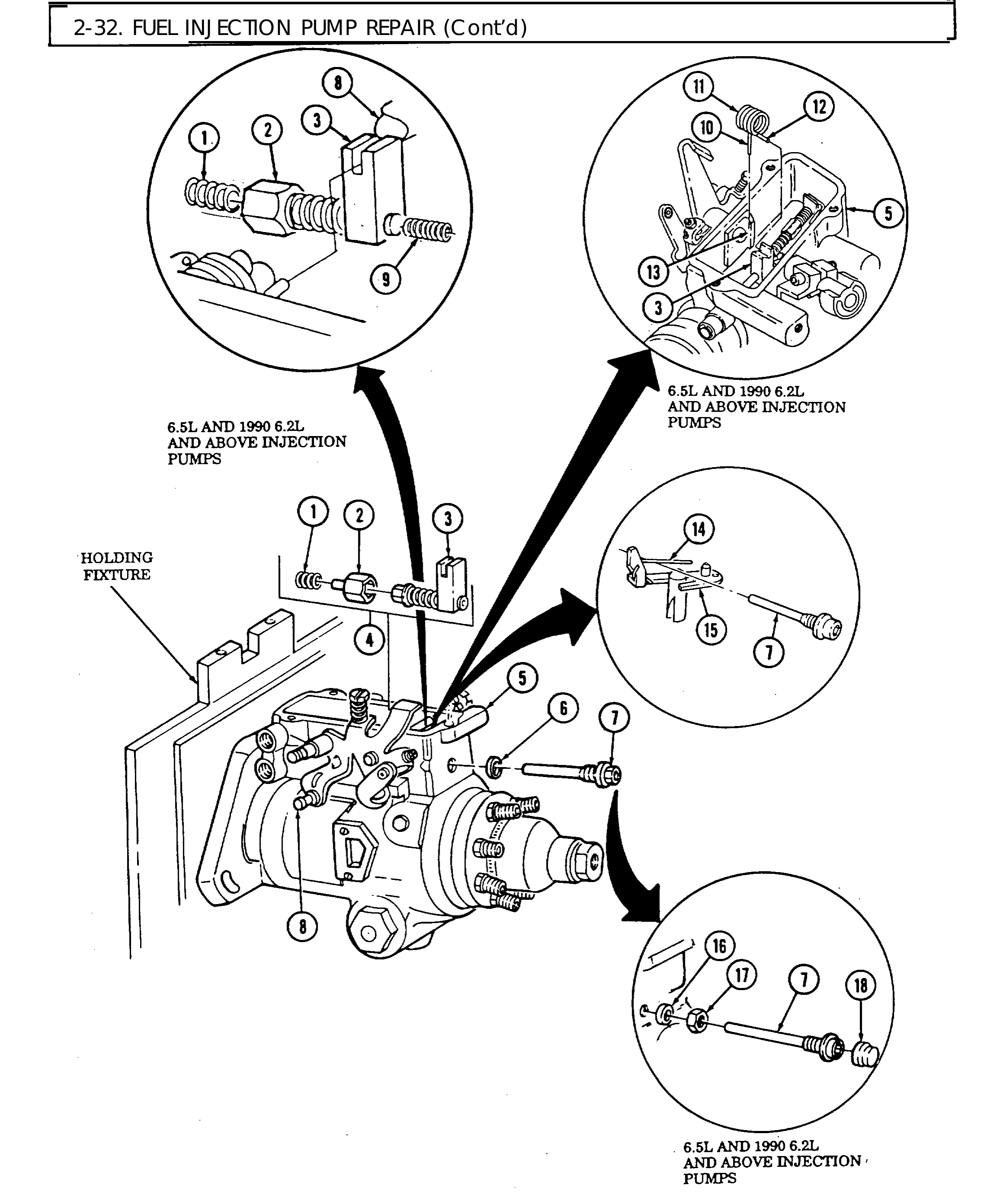
5. Remove cap (8) from guide stud (7). Using 1/4-in. hex head driver, remove guide stud (7), seal (5), and nut (6) from min-max governor (12). Discard seal (5) and cap (8).
6. Turn throttle shaft (11) to low idle and remove idle spring (16).
7. Turn throttle shaft (11) to wide open throttle, loosen sleeve (17) on min-max governor (12) and lift min-max governor (12) and inner governor spring (14) out of pump (9) and disengage min-max governor (12) from governor thrust spring (15).
8. Using 1/4-in. hex head driver, remove guide stud (7) and washer (10) from min-max governor (12). Discard washer (10).
9. Turn throttle shaft (11) to wide open throttle and pull min-max governor (12) out of pump (9).
Some 6.5LPUMP REPAIR injection pumps(Cont'd) are equipped with a TP sensor instead of a kick-down switch. There are four capscrews securing the TP sensor to the housing.
10. Deleted.
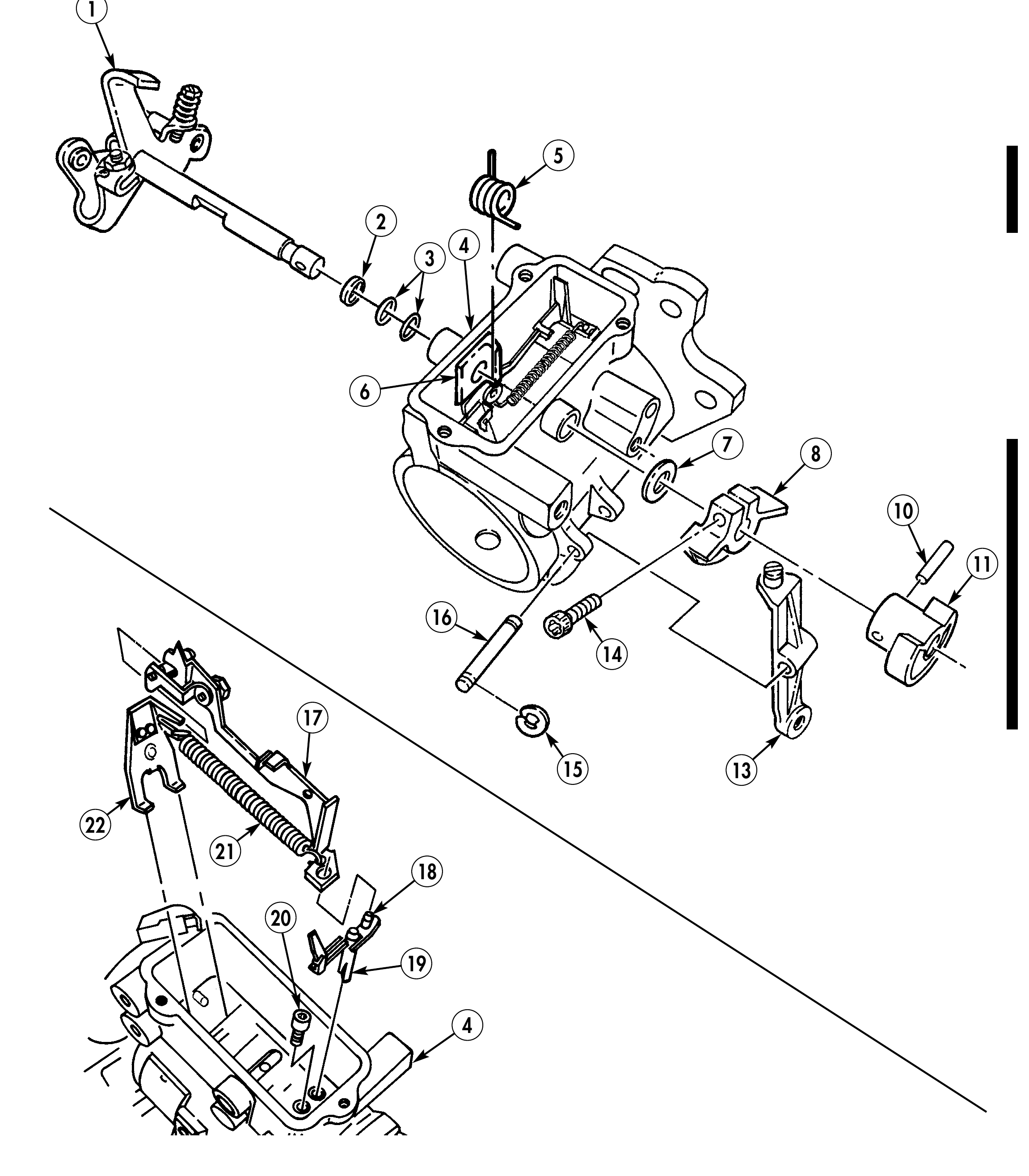
11. Remove cam pin (10) and cam (11) from throttle shaft (1).
12. Remove two retaining clips (15) from rocker lever pin (16). Discard clips (15).
13. Remove rocker lever pin (16) and rocker lever (13) from housing (4).
14. Using Torx drive, remove screw (14) from face cam (8) and remove face cam (8) and washer (7) from throttle shaft (1).
15. Turn throttle shaft (1) to low idle and release the governor thrust spring (5) from housing boss (6).
16. Remove throttle shaft (1) and governor thrust spring (5) from housing (4), and remove two O-rings (3) and spacer (2) from throttle shaft (1). Discard O-rings (3).
17. Remove throttle shaft (1) from housing (4), and remove two O-rings (3) and spacer (2) from throttle shaft (1). Discard O-rings (3).
18. Hold metering valve (19) and raise governor linkage hook (17) from valve arm pin (18).
19. Hold governor arm (22) forward and pull linkage hook (17) back and detach from governor arm (22).
20. Remove linkage hook (17), governor arm (22), and spring (21) from housing (4).
21. Remove spring (21) from linkage hook (17) and governor arm (22).
22. Remove metering valve (19) from housing (4).
23. Using 1/8-in. hex head driver, remove vent wire socket head screw (20) from housing (4).
7 8
15 13
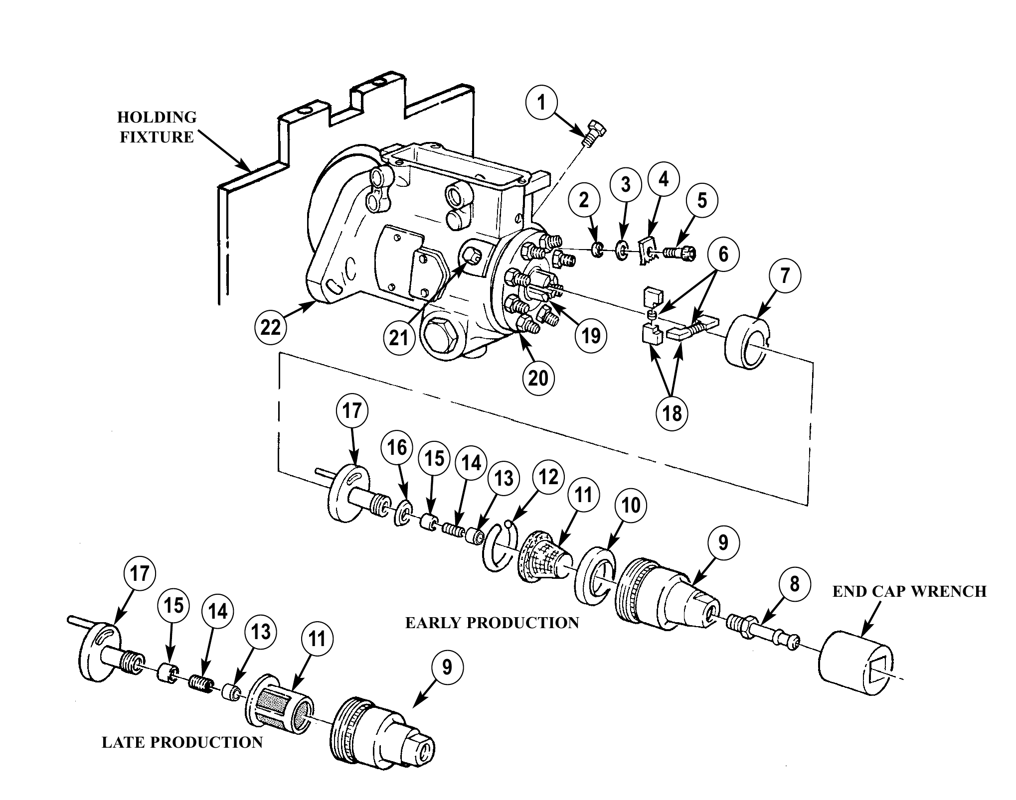
24. Using 5/32-in. hex head driver, remove transfer pump end cap socket-head locking screw (5), plate (4), rubber washer (2), and flat washer (3) from hydraulic head (20). Discard washer (2).
25. Remove inlet tube assembly (8) from fuel pump end cap (9).
26. Using end cap wrench, remove fuel pump end cap (9) from hydraulic head (20).
27. Remove regulator (17) from fuel pump end cap (9).
28. Remove inlet filter screen (11) and pressure plate (10), if applicable, from regulator (17).
29. Remove retaining ring (12) and screen (11) from pressure plate (10), if applicable.
30. Remove inlet filter screen seal (16), end plate adjusting plug (13), spring (14), and piston (15) from regulator (17). Discard adjusting plug (13) and seal (16). Tag spring (14) and piston (15) for assembly.
31. Remove transfer pump liner (7), four blades (18), and two springs (6).
32. Remove head-locking capscrews (1) and (21) from housing (22).
HOLDING FIXTURE
3 4 2 5
22 21 19 17 18 16 15 13 12 11 10 8 END CAP WRENCH 15 14 EARLY PRODUCTION 13 11
LATE PRODUCTION
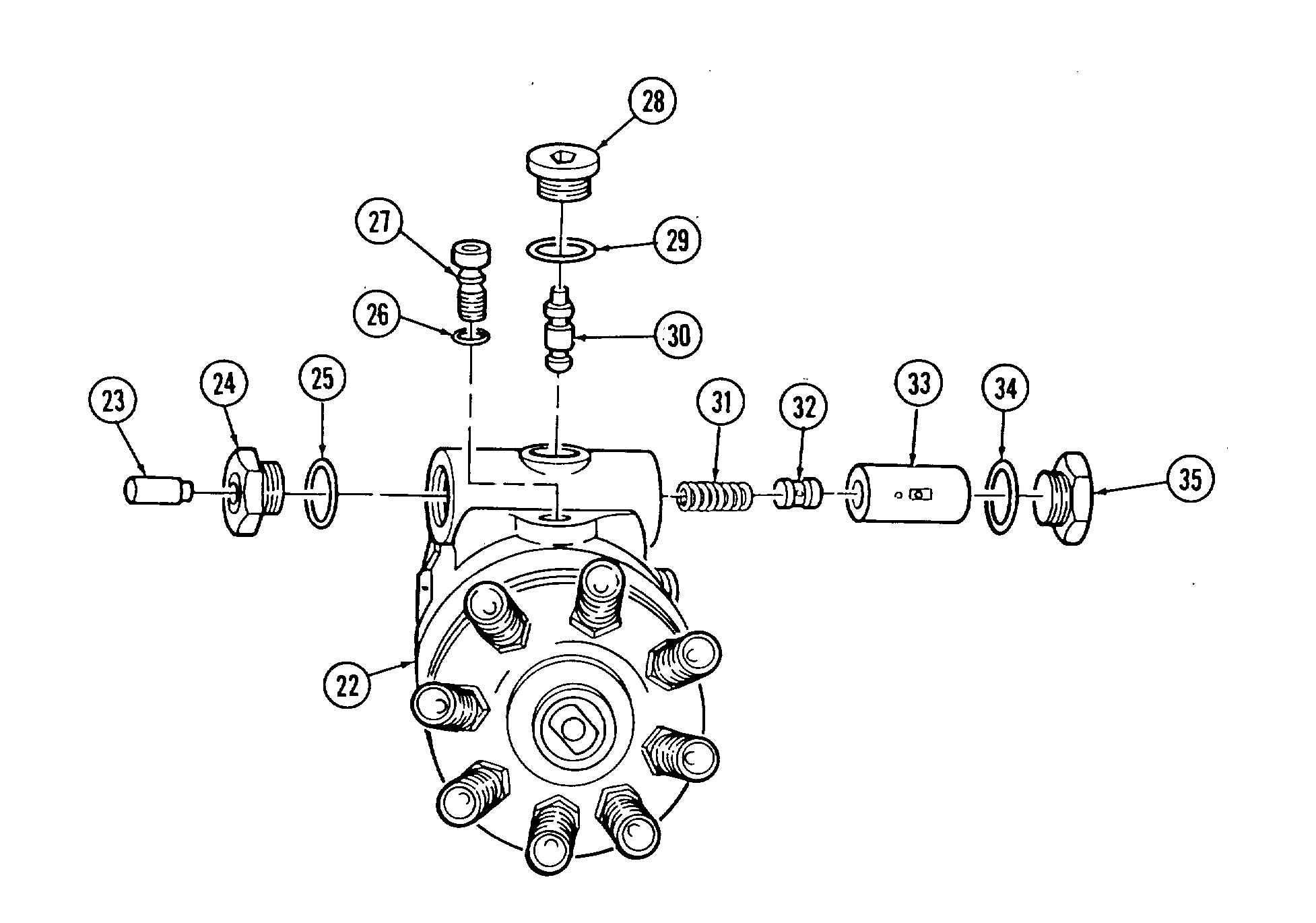
33. Rotate housing (22) and holding fixture in vise so advance plug (28) faces upward.
34. Using 5/16-in. hex head driver, remove head locating screw (27) and O-ring (26). Discard O-ring (26).
35. Remove spring side plug assembly (24) and O-ring (25) from housing (22). Disard O-ring (25).
36. Remove servo advance plunger (23) from spring side plug (24).
37. Using 1/4-in. hex head driver, remove advance plug (28), cam advance pin (30), and O-ring (29) from housing (22). Discard O-ring (29).
38. Remove power side advance piston hole plug (35) and O-ring (34). Discard O-ring (34).
39. Remove servo advance piston assembly (33) from housing (22). Tap piston assembly (33) to remove spring (31) and valve (32). Tag spring (31) for assembly.
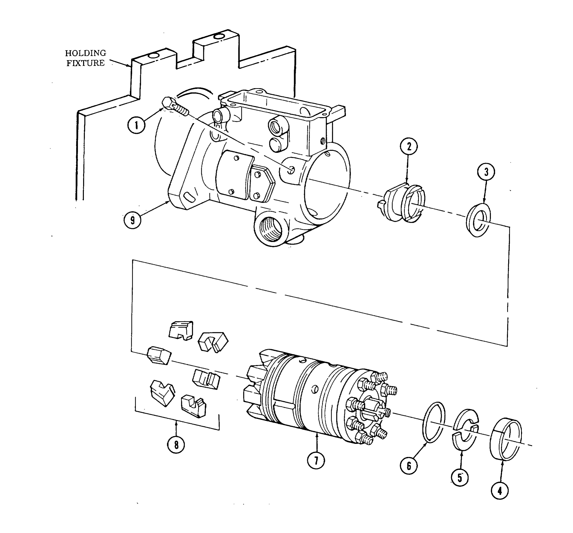
40. Rotate housing (9) and holding fixture right side up.
41. Remove head locking capscrew (1).
42. Remove hydraulic head assembly (7) from housing (9).
43. Remove six weights (8), washer (3), and governor thrust sleeve (2) from hydraulic head (7).
44. Remove liner locating ring (4) and two rotor retainers (5) from hydraulic head (7).
45. Remove transfer pump end cap seal (6) from hydraulic head (7). Discard seal (6).
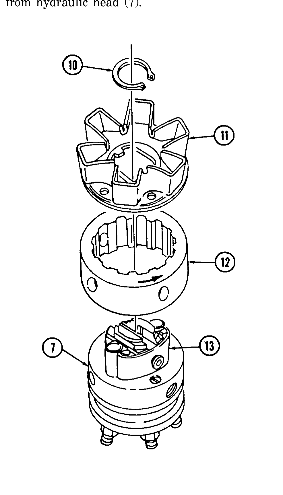
46. Remove snapring (10) and weight retainer (11) from rotor (13).
47. Remove cam ring (12) from hydraulic head (7).
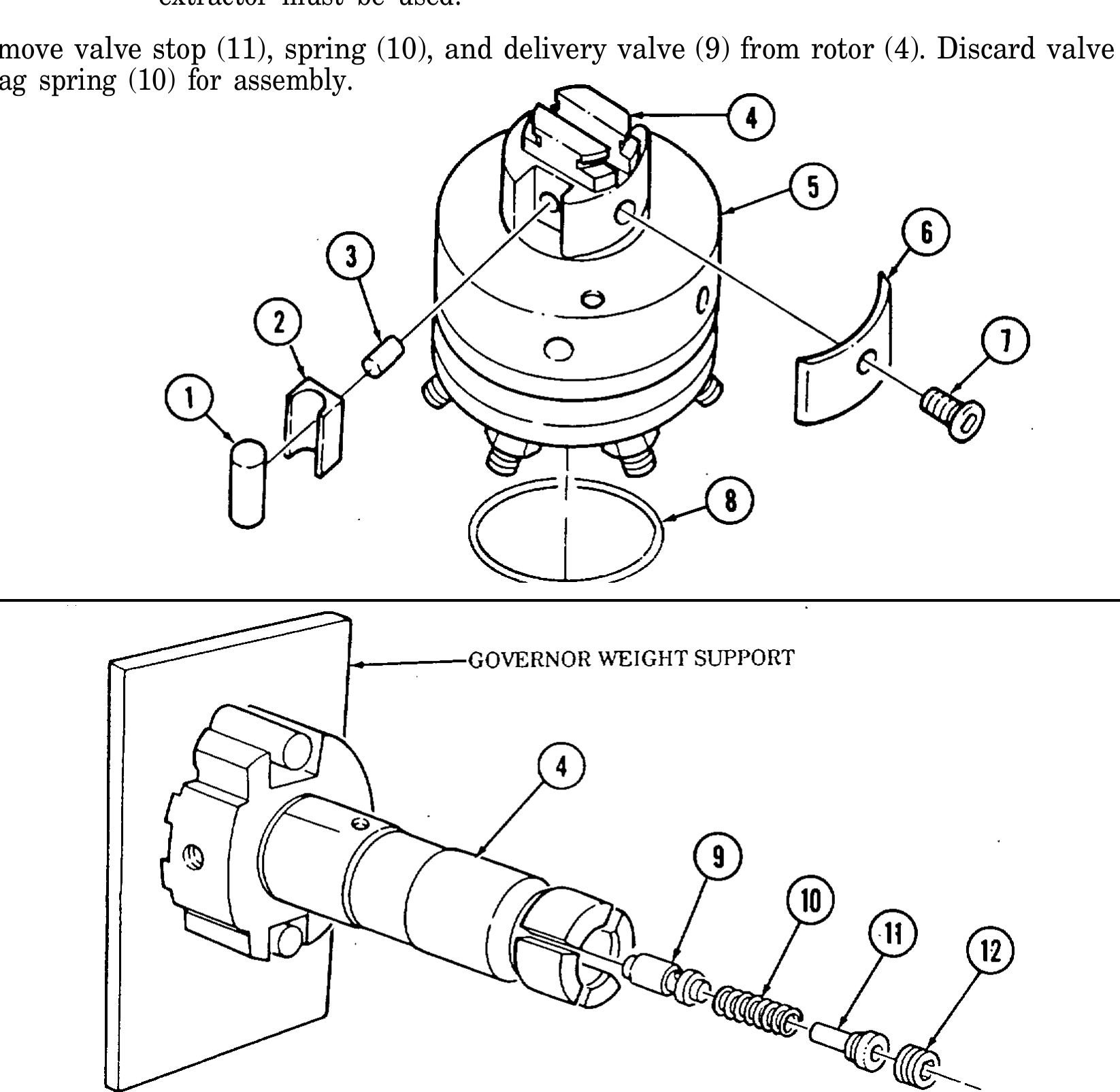
48. Remove two cam roller shoes (2) and two cam rollers (1) from rotor (4).
49. Remove leaf spring adjusting screw (7) and leaf spring (6) from rotor (4).
50. Remove two plungers (3) from rotor (4).
51. Install governor weight support in vise.
52. Remove rotor (4) from hydraulic head (5) and place rotor (4) in governor weight support. Using 5/32-in. hex head driver, remove delivery valve stop plug (12).
53. Remove head seal (8) from hydraulic head (5). Discard head seal (2).
54. Remove valve stop (11), spring (10), and delivery valve (9) from rotor (4). Discard valve stop (11) and tag spring (10) for assembly.
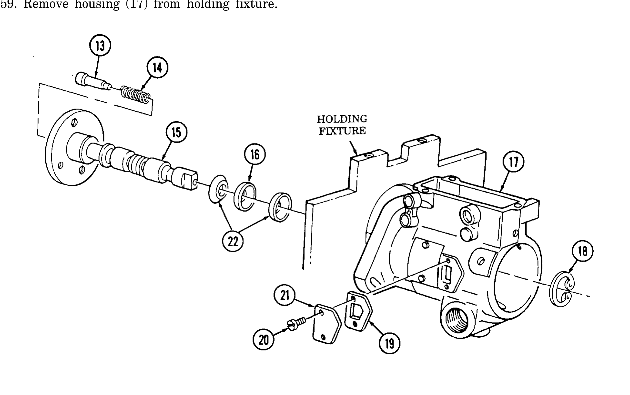
55. Remove drive shaft snapring (18) and drive shaft (15) from housing (17).
56. Remove two black seals (22) and red seal (16) from drive shaft (15). Discard seals (22) and (16).
57. Remove thrust button (13) and spring (14) from drive shaft (15) and tag spring (14) for assembly.
58. Remove two screws (20), timing cover (21), and gasket (19) horn housing (17). Discard gasket (19).
59. Remove housing (17) from holding fixture.
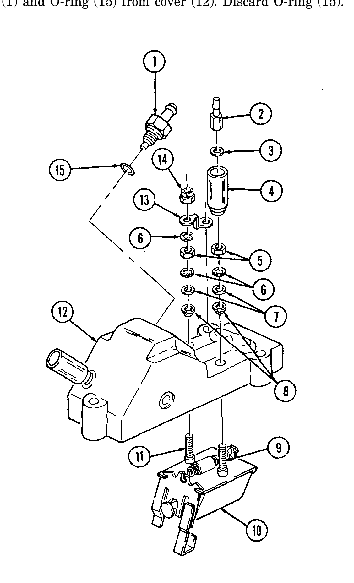
60. Remove terminal (2), washer (3), and shell (4) from stud (9).
61. Remove nut (5), lockwasher (6), washer (7), and fiber washer (8) from stud (9). Discard lockwasher (6).
62. Remove locknut (14), ground strap (13), lockwasher (6), nut (5), lockwasher (6), washer (7), and fiber washer (8) from stud (11). Discard locknut (14) and lockwashers (6).
63. Remove electrical shutoff solenoid (10) from cover (12).
64. Remove check valve (1) and O-ring (15) from cover (12). Discard O-ring (15).
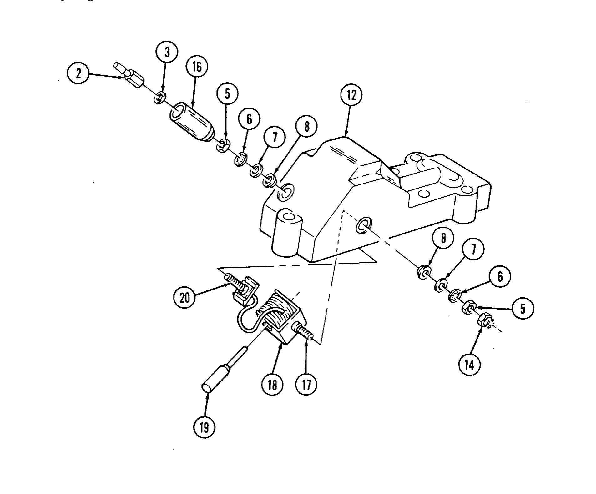
65. Remove terminal (2), washer (3), and shell (16) fromstud (20).
66. Remove nut (5), lockwasher (6), washer (7), and fiber washer (8) from stud (20). Discard lockwasher (6).
67. Remove locknut (14), nut (5), lockwasher (6), washer (7), and fiber washer (8) from stud (17). Discard lockwasher (6) and locknut (14).
68. Remove cold advance solenoid (18) and plunger (19) from cover (12).
69. Remove plunger (19) from cold advance solenoid (18).
b. Cleaning
fluid to avoid contamination. ● Do not immerse hydraulic head in solvent or sealant damage
may result.
1. Clean all fuel injection pump components in accordance with instructions in para. 2-9.
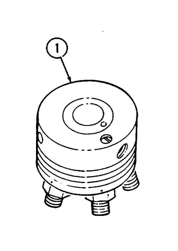
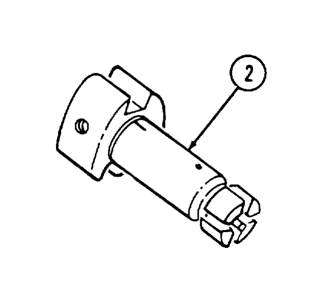
2. Rinse hydraulic head (1) and rotor (2) in calibrating fluid.
c. Inspection
1. Inspect housing (5) for damage. Replace injection pump if damaged.
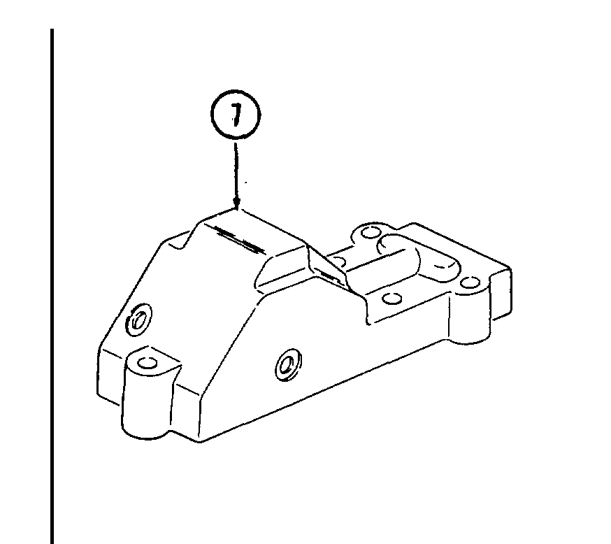
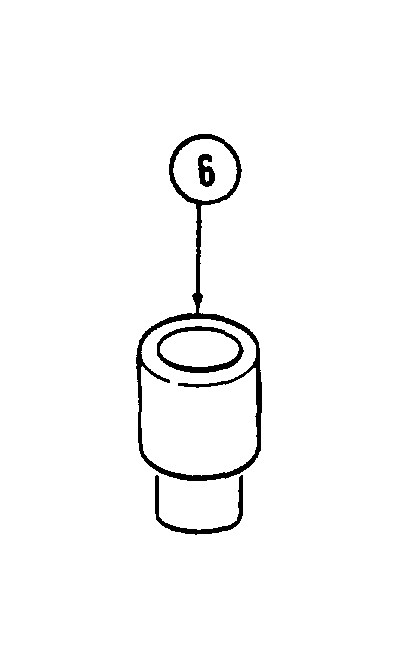
2. Inspect pilot tube (4) in housing (5) for scoring or damage. If scored or damaged, perform steps 3 through 7, if not, go to step 8.
3. Remove pilot tube (4) and drive shaft bearing (3) from housing (5) using pilot tube mandrel. Discard pilot tube (4).
4. Inspect drive shaft bearing (3) for roughness or damage. Discard if rough or damaged.
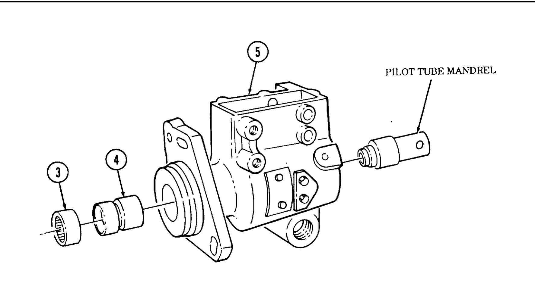
5. Apply sealing compound to outside diameter of pilot tube (4).
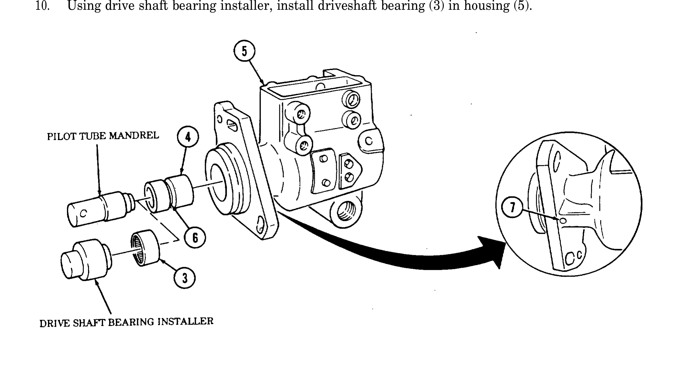
6. Using pilot tube mandrel, install pilot tube (4) in housing (5) until groove (6) in pilot tube (4) aligns with vent hole (7) in housing (5).
7. Using drive shaft bearing installer, install drive shaft bearing (3) in housing (5). Go to step 11.
8. Inspect drive shaft bearing (3) for roughness or damage. If rough or damaged, perform steps 9 and 10. If not, go to step 11.
9. Remove drive shaft bearing (3) from housing (5) and discard bearing (3).
10. Using drive shaft bearing installer, install driveshaft bearing (3) in housing (5).
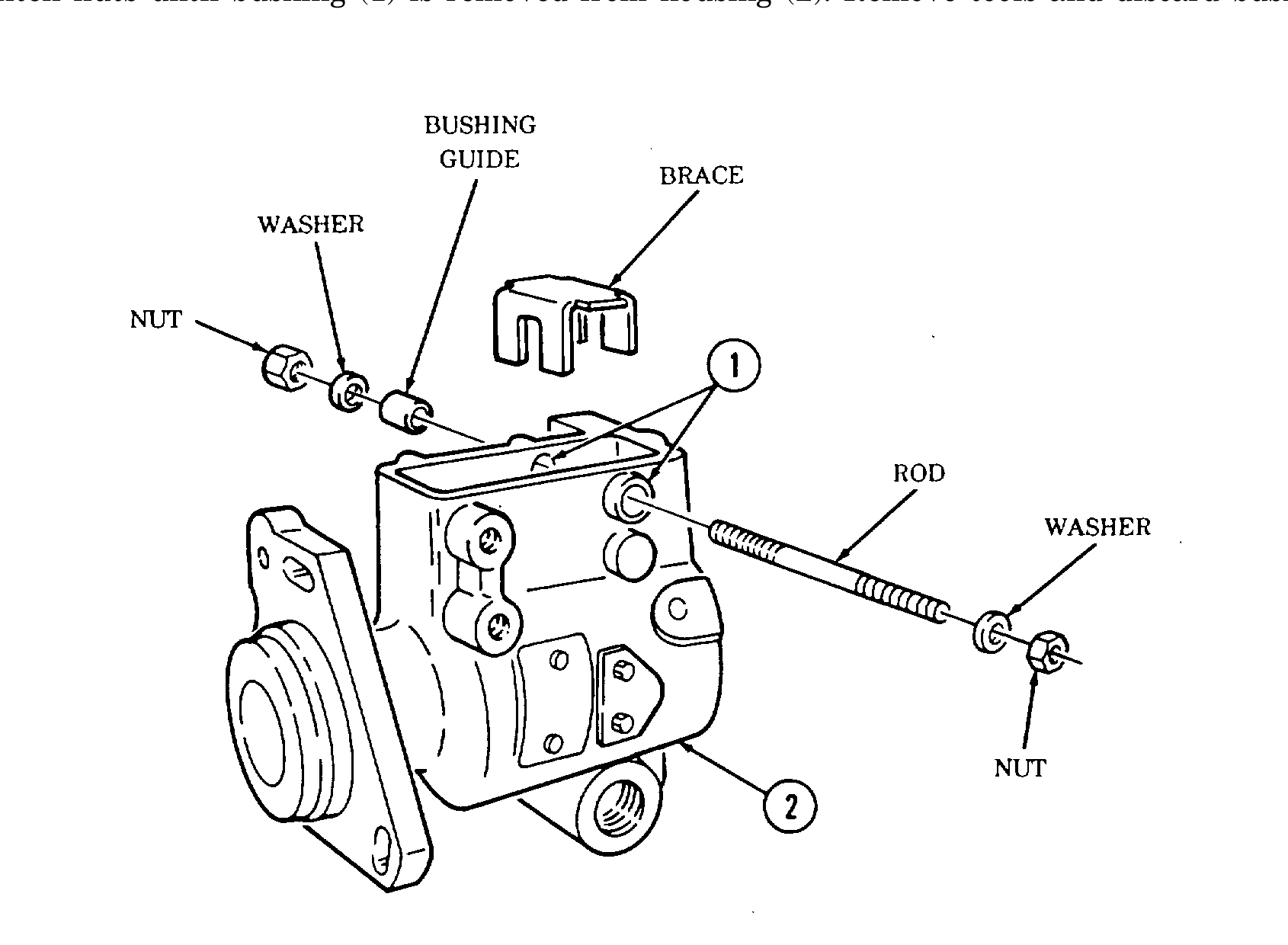
11. Inspect throttle shaft bushings (1) for damage. If damaged, perform steps 12 through 20 using throttle and shutoff shaft bushing installation kit. If not, go to step 21.
12. Install brace into housing (2) to prevent distortion of housing (2) during bushing (1) removal.
13. Install rod through bushings (1).
14. Install bushing guide, two washers, and nuts.
15. Tighten nuts until bushing (1) is removed from housing (2). Remove tools and discard bushing (1).
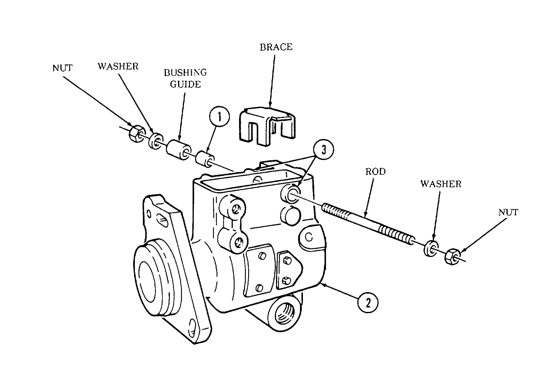
16. Install brace and rod into housing (2).
17. Apply sealing compound to outside diameter of bushing (1).
18. Install bushing (1), bushing guide, two washers, and nuts on rod.
19. Tighten nuts until bushing (1) is past flush with bushing boss (3) on housing (2). Remove tools from housing (2).
20. Repeat steps 12 through 19 for opposite bushing, if required.
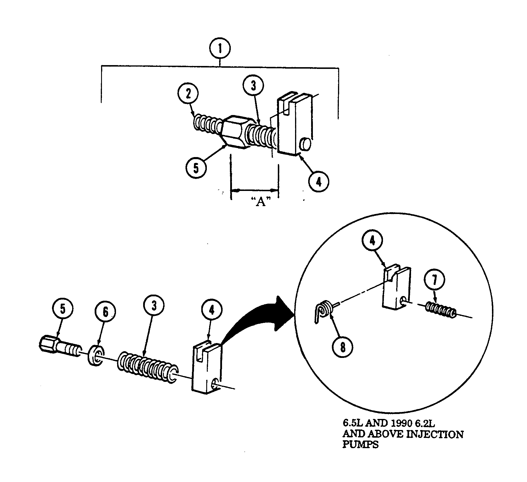
21. Inspect idle spring (2) on min-max governor (1) for corrosion or damage. Replace if corroded or damaged.
22. Inspect inner governor spring (7) for corrosion or damage. Replace if corroded or damaged.
23. Inspect governor thrust spring (8) for corrosion or damage. Replace if corroded or damaged.
24. Inspect min-max spring (3) for corrosion or damage. If corroded or damaged, perform steps 25 through 29. If not, go to step 30.
25. Remove idle spring (2) from pushrod (5).
26. Measure distance “A” from throttle block (4) to end of pushrod (5) for assembly.
27. Put throttle block (4) in vise and remove pushrod (5), spring (3), and washer (6). Discard spring (3).
28. Install washer (6) and spring (3) on pushrod (5) and install into throttle block (4).
29. Tighten pushrod (5) until measurement taken in step 26 is obtained.
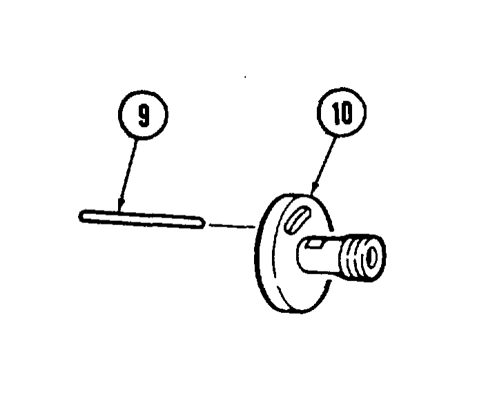
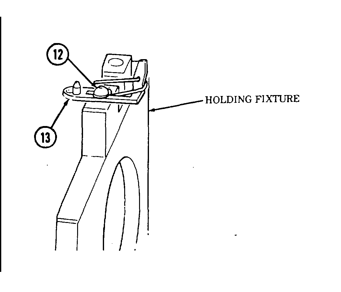
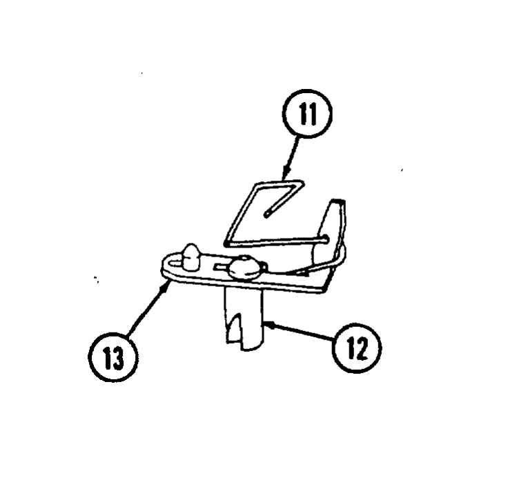
30. Inspect regulatar (10) for damage. Replace if damaged.
31. Inspect roll pin (9) in regulator (10) for damage. Replace if damaged.
32. Inspect arm spring (11) for damage. Replace if damaged.
33. Inspect metering valve (12) and arm (13) for damage. If damaged, perform steps 34 and 35. If not, go to step 36.
34. Place valve (12) in holding fixture hole and remove arm (13) from valve (12).
35. Install arm (13) on valve (12).
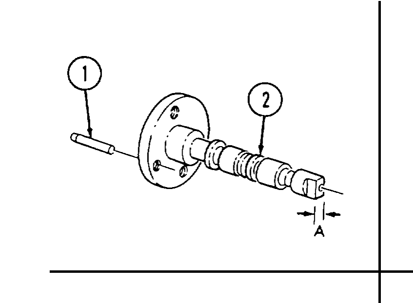
36. Using a micrometer, measure drive shaft (2) at point “A” to determine wear. Inspect drive shaft (2) seal area for nicks, burrs, scratches, or damage. Replace drive shaft (2) if measurement at point “A” is less than 0.305 in. (7.75 mm) or if any nicks, burrs, scratches, or damage is present.
37. Inspect dowel pin (1) in drive shaft (2) for damage. If damaged, replace dowel pin (1). Apply sealing compound to replacement dowel pin (1).
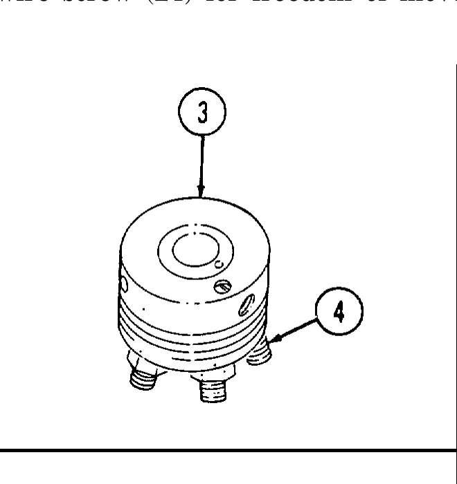
38. Inspect fittings (4) in hydraulic head (3) for damage. Replace hydraulic head (3) and rotor (13) if any fittings (4) are damaged.
39. Inspect hydraulic head (3) and rotor (13) for damage. Replace both if either is damaged.
40. Inspect charging ports (11) and discharge port (12) on rotor (13) for chipped edges. Replace hydraulic head (3) and rotor (13) if any chipped edges are apparent.
41. Inspect rotor (13) for scratches. Replace hydraulic head (3) and rotor (13) if scratches are present.
Do not allow solvents to get on skin or clothing. Solvents can burn easily and give off harmful vapors. Keep away from open fire and use in a well-ventilated area. If solvent gets on skin or clothing, wash immediately. Failure to follow these instructions could cause injury or death.
42, While holding rotor (13) under clean calibrating fluid, insert plungers (10) into bores of rotor (13). With thumb and forefinger over roller shoe (9) slots, tilt from side to side to determine freedom of movement. If the plungers (10) are sticking, but not visibly damaged, clean both plungers (10) and bore with a soft brush and lacquer thinner or acetone. Check freedom of movement again. If plungers (10) still stick, replace them with the next smaller size (“A” is the largest, “D” is the smallest). If the smallest plungers (10) stick in rotor (13), replace hydraulic head (3) and rotor (13).
43. Inspect leaf spring contact area (14) and tang slot (7) on rotor (13) for excessive wear. Replace hydraulic head (3) and rotor (13) if leaf spring contact area (14) or tang slot (7) are excessively worn.
44. Inspect cam rollers (8) for freedom of rotation in their roller shoes (9). Inspect cam rollers (8) and roller shoes (9) for abrasive wear patterns. Replace cam rollers (8) and roller shoes (9) if cam rollers (8) do not rotate freely or if either shows signs of abrasive wear patterns.
45. Inspect top edge of each roller shoe (9) for chipping or excessive wear. Replace cam rollers (8) and roller shoes (9) if chipped or excessively worn.
46. Inspect leaf spring (6) for excessive wear. Replace leaf spring (6) if excessively worn.
47. Inspect leaf spring screw (5) for tightness in rotor (13). Replace leaf spring screw (5) if screw (5) does not thread tightly into rotor (13).
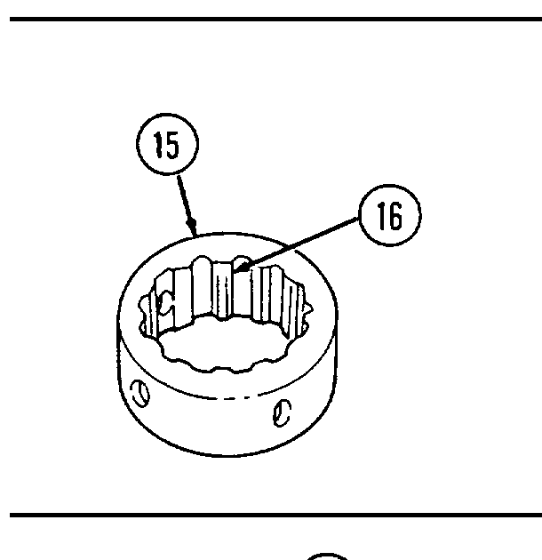
48. Inspect cam lobes (16) on cam ring (15) for spalling or flaking out. Replace cam ring (15) if cam lobes (16) are spalled or flaked.
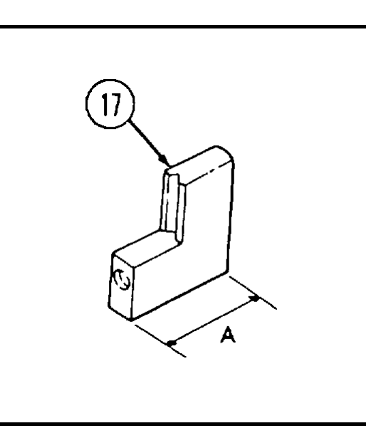
49. Inspect all transfer pump blades (17) and transfer pump liner (18) for scoring or damage. Replace all transfer pump blades (17) and transfer pump liner (18) if any are scored or damaged.
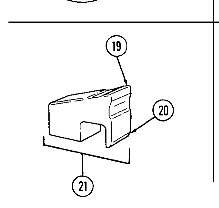
50. Using a micrometer, measure transfer pump blades (17) at point “A” to determine wear. If any transfer blade (17) is smaller than 0.538 in. (13.67 mm), replace all transfer pump blades (17) and transfer pump liner (18).
51. Inspect governor weights (21) for excessive wear at heel (19) and toe (20) Replace governor weights (21) if excessively worn.
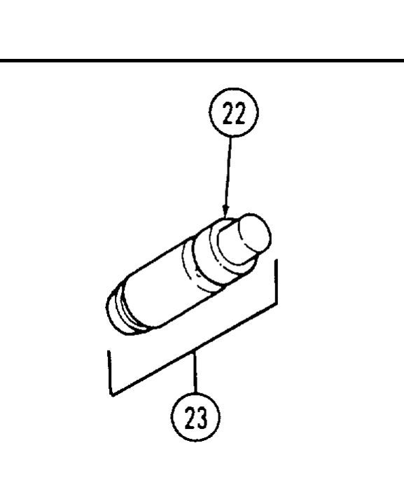
52. Inspect delivery valve reaction cuff (22) for chipping or erosion. Replace delivery valve (23) if reaction cuff (22) is chipped or eroded.
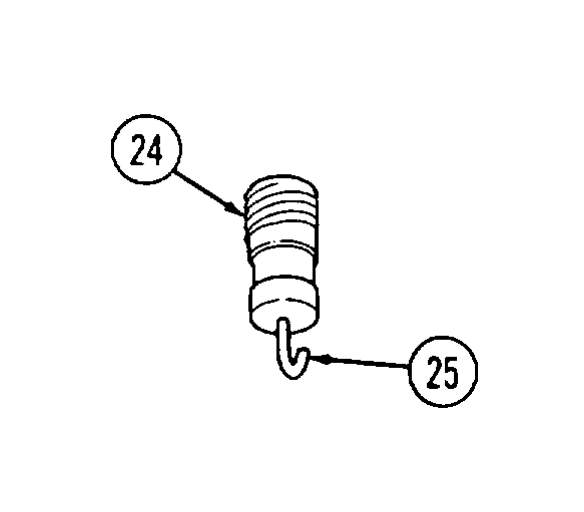
53. Inspect vent wire (25) in vent wire screw (24) for freedom of movement. If vent wire (25) is stuck, replace vent wire screw (24).
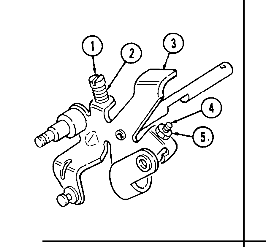
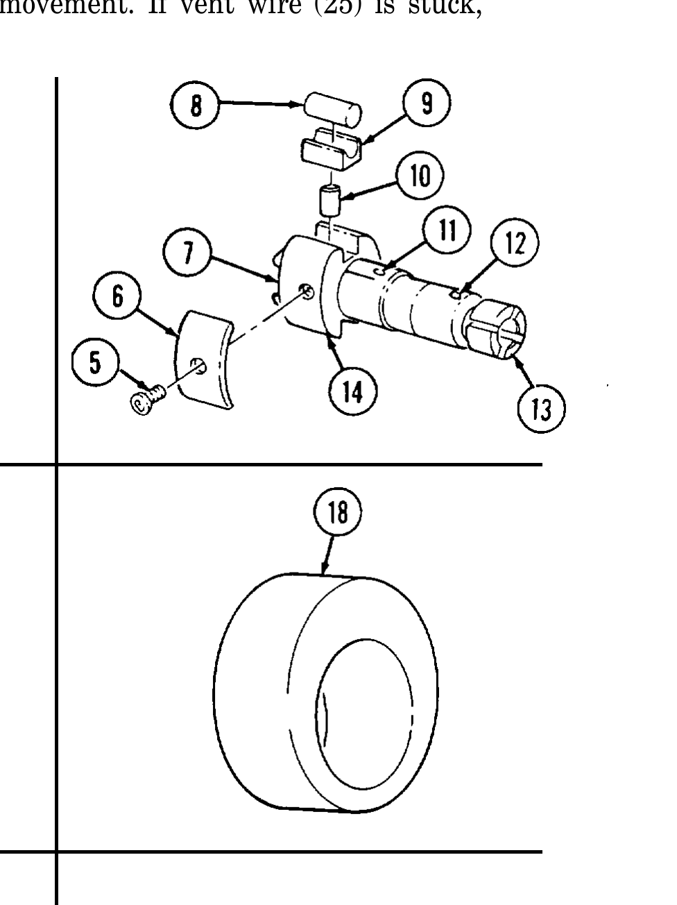
54. Inspect throttle shaft (3) for distortion or damage. Replace if distorted or damaged.
55. Install low idle screw (1), spring (2), max travel screw (4), and nut (5) in throttle shaft (3).
56. Inspect rubber connectors (6) for deterioration, cracks, or damage. Replace if cracked, deteriorated, or damaged.
57. Inspect pump cover (7) for damage. Replace if damaged.
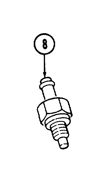
58. Inspect check valve (8) for damage. Replace if damaged.
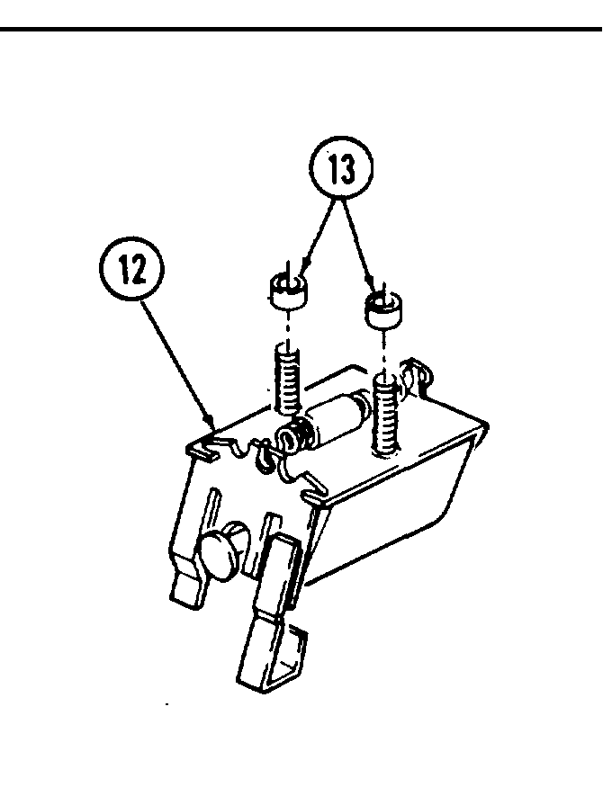
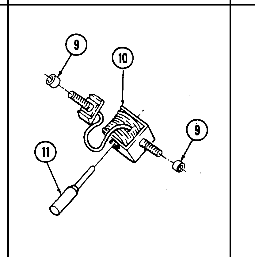
59. Inspect cold start advance solenoid (10) for damage. Replace if damaged.
60. Inspect insulators (9) and plunger (11) for damage, Replace if damaged,
61. Inspect insulators (13) and electrical shutoff solenoid (12) for damage. Replace if damaged.
62. Refer to para. 2-10 for general inspection instructions for all other injection pump parts.
d. Assembly
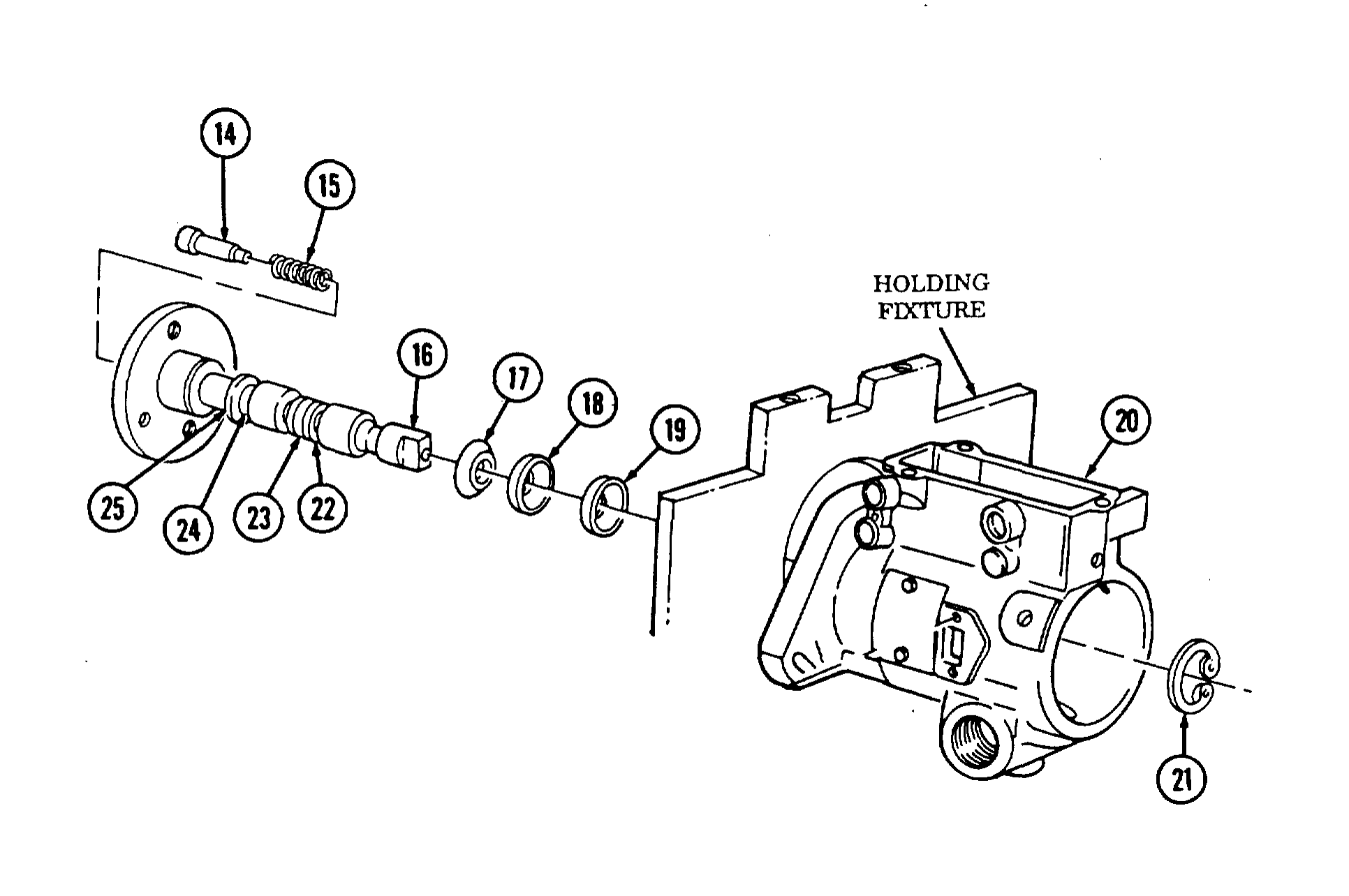
1. Mount injection pump housing (20) in holding fixture and secure with vise.
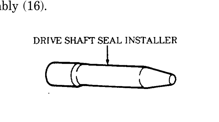
2. Lubricate seals (17), (18), and (19) with seal lubricant and install black seal (17) in groove (25), red seal (18) in groove (24) and black seal (19) in groove (23) using drive shaft seal installer.
3. Install thrust button spring (15) and thrust button (14) in drive shaft assembly (16).
Note position of timing mark on end of drive shaft tang when installing drive shaft assembly. This is necessary to align rotor to drive shaft.
4. Install drive shaft assembly (16) in housing (20).
5. Install snapring (21) in groove (22) on drive shaft assembly (16).
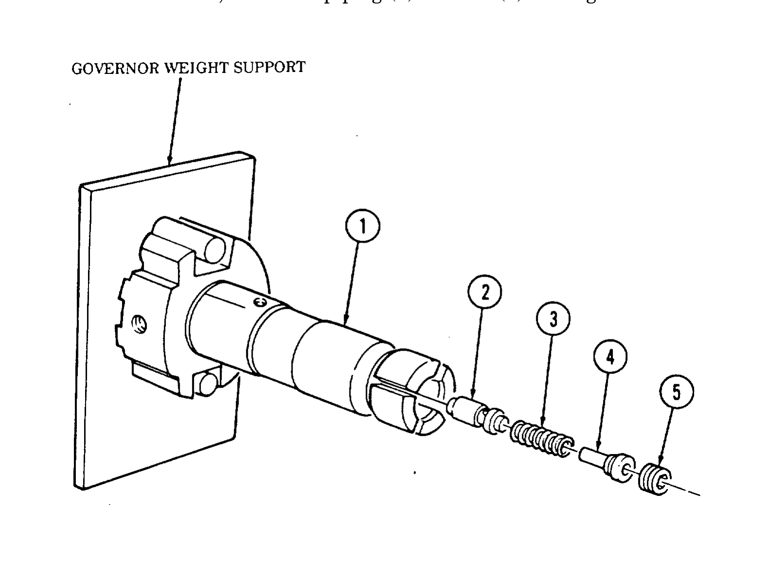
fluid to avoid contamination.
6. Mount governor weight support in vise and rinse rotor (1) in calibrating fluid and install in support.
delivery valve.
7. Install delivery valve (2) in rotor (1).
8. Install valve spring (3) and valve stop (4) in rotor (1).
9. Using 5/32-in. hex head driver, install stop plug (5) in rotor (1) and tighten to 85-90 lb-in. (10 N•m).
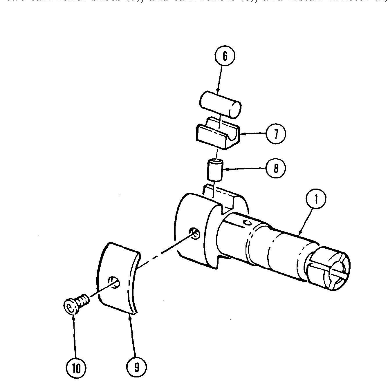
10. Install leaf spring (9) and adjusting screw (10) on rotor (1).
11. Remove rotor (1) from governor weight support and submerge in calibrating fluid.
fit sizes: A, B, C, and D. The rotor is etched with the letter indi- cating bore size. This mark is found on the base of the rotor. ● If plunger replacement is required, check the size designation on
the rotor and use the plunger of corresponding part number as indicated by letter designation on rotor.
12. Install two plungers (8) in rotor (1).
13. Assemble two cam roller shoes (7), and cam rollers (6), and install in rotor (1).
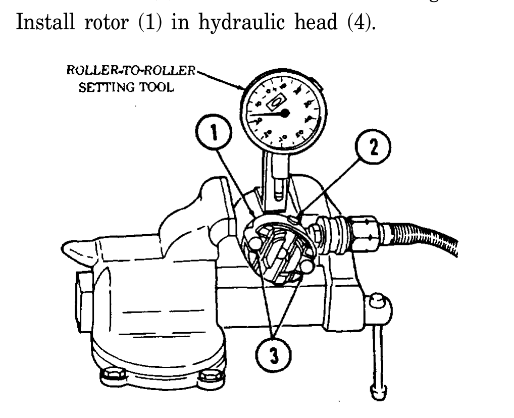
14. Install roller-to-roller setting tool in soft-jaw vise.
15. Install roller (1) in roller-broiler setting tool.
16. Apply compressed air regulated to 40-100 psi (276-689 kPa) to roller-broiler setting tool.
17. Measure roller-to-roller dimension and compare to pump specification 1.981 in. (50.31 mm).
18. Turn leaf spring adjusting screw (2) clockwise to increase or counterclockwise to decrease roller- to-roller dimension.
19. Rotate rotor (1) until one cam roller (3) aligns with roller-to-roller setting tool dial indicator plunger.
20. Loosen indicator dial retaining screw and set preload by sliding indicator down until plunger depresses on cam roller (3) 0.015 in. (0.381 mm). Tighten screw. Rotate dial on indicator to “zero” indicator on high point of cam roller (3).
22. Measure cam roller centrality by rotating rotor (1) in either direction until high point of other cam roller (3) depressed dial indicator plunger. Indicator reading should be 0.000 in. to 0.008 in. (0.000 to 0.203 mm).
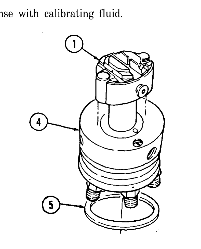
23. Rinse hydraulic head (4) with calibrating fluid.
24. Remove rotor (1) from roller-to-roller setting tool and rinse with calibrating fluid.
25. Install rotor (1) in hydraulic head (4).
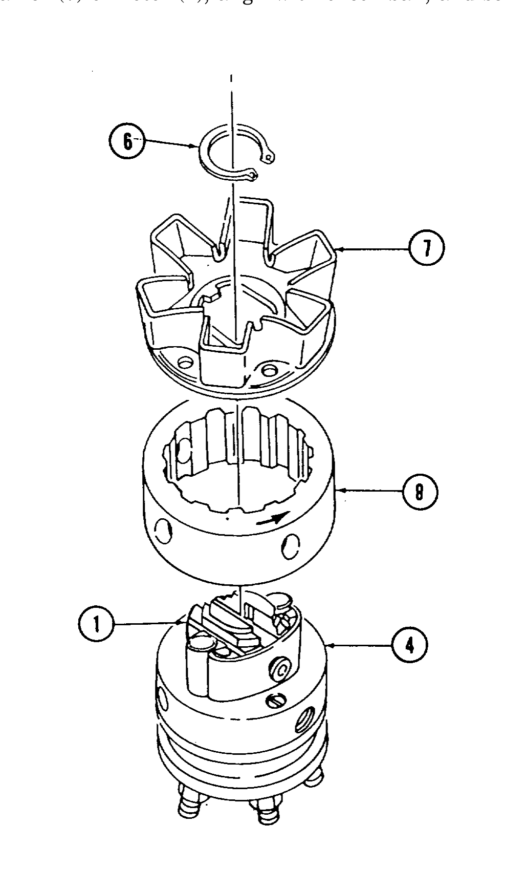
26. Install head seal (5) on rotor (4).
27. Install cam ring (8) on hydraulic head (4) with directional arrow on ring showing counterclockwise rotation of pump rotor (1).
28. Install weight retainer (7) on rotor (1), align with check ball, and secure with snapring (6).
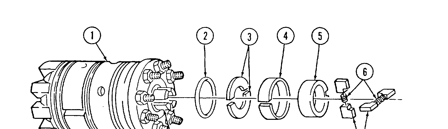
29. Install transfer pump end cap seal (2) in hydraulic head (1).
Use care when handling rotor weight retainer and hydraulic head before retainers are installed. Rotor can fall out and cause damage to components.
30. Install two rotor retainers (3) with cut out portions meeting over roll pin hole in hydraulic head (1).
31. Install liner locating ring (4) on hydraulic head (1) with split 90° from roll pin hole.
32. Install transfer pump liner (5) so slot aligns with roll pin hole in hydraulic head (1).
Oversize blades are marked in black and must be used whenever possible. ● Oversize and standard transfer pump blades do not have to be
used as matched sets.
33. Install two springs (6) in four transfer pump blades (7) and install transfer pump blades (7) in rotor (8).
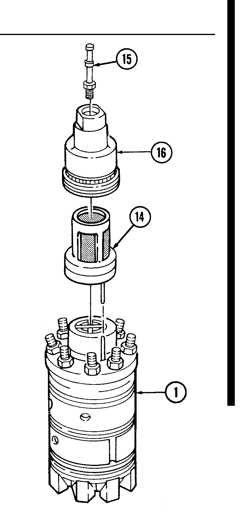
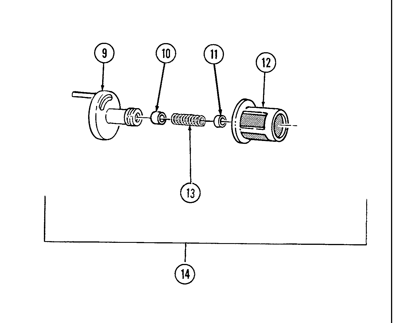
34. Install piston (10), spring (13), and adjusting plug (11) in regulator (9). Tighten adjusting plug (11) until flush with end of regulator (9).
35. Deleted
36. Install filter screen (12) on regulator (9).
37. Lightly coat filter screen assembly (14) and threads of transfer end cap (16) with seal lubricant.
38. Install filter screen assembly (14) and end cap (16) on hydraulic head (1). Apply slight pressure on top of end cap (16) and rotate counterclockwise until a slight click is heard.
39. Turn end cap (16) clockwise until snug.
40. Install inlet tube assembly (15) on end cap (16).
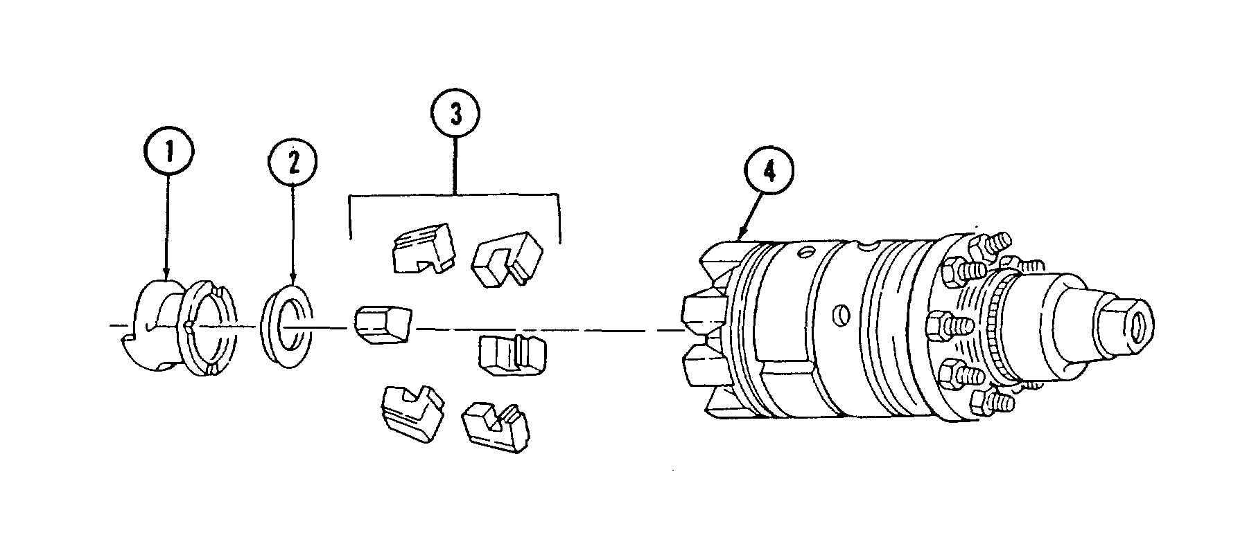
41. Install six governor weights (3) in weight retainer (4).
42. Install thrust washer (2) and thrust sleeve (1) into lower slots of governor weights (3).
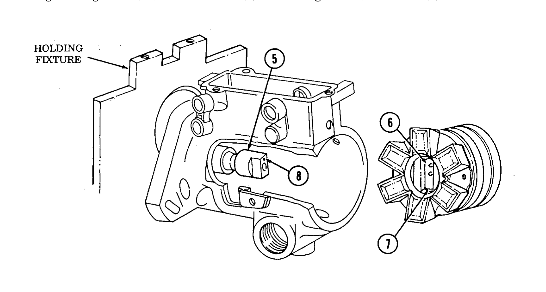
43. Align timing mark (11) on drive shaft (5) and timing mark (6) on rotor (7).
44. Apply light coat of seal lubricant to inside edge of housing (12).
45. Rotate cam ring (9) so index mark (11) is aligned with timing cover access hole (13).
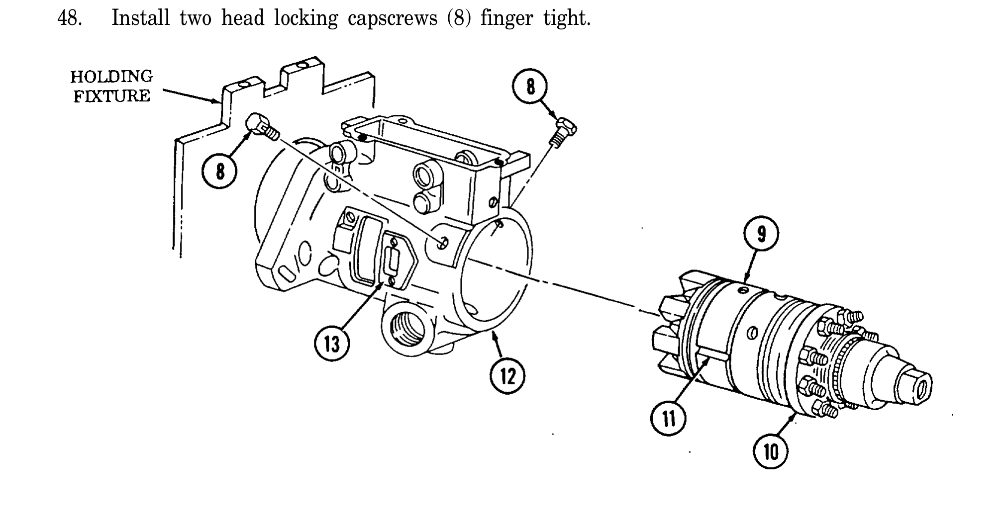
46. Install hydraulic head (10) in housing (12) with slight rotary motion.
47. Rotate head (10) and align head locking capscrew holes with holes in housing (12).
48. Install two head locking capscrews (8) finger tight.
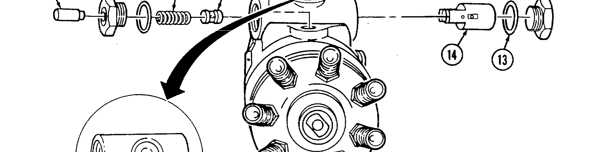
49. Rotate housing (11) and holding fixture in vise so advance plug (8) faces up.
50. Install O-ring (6) on head locating screw (7).
51. Lightly coat head locating screw (7) with seal lubricant and install in housing (11). Tighten screw (7) to 180-220 lb-in. (20-25 N•m) using 5/16-in. hex head driver.
52. Install servo advance piston (14) in housing (11) with notch and two small holes facing head locating screw (7).
53. Install O-ring (13) and power side advance piston hole plug (12) in housing (11). Tighten plug (12) to 215-265 lb-in. (24-30 N•m).
54. Install cam advance pin (10).
55. Install O-ring (9) and advance plug (8) in housing (11). Tighten advance plug (8) with 1/4-in. hex head driver to 75-100 lb-in. (9-11 N•m).
56. Install servo advance valve (5) on spring (4) and install servo advance valve (5) in servo advance piston (14).
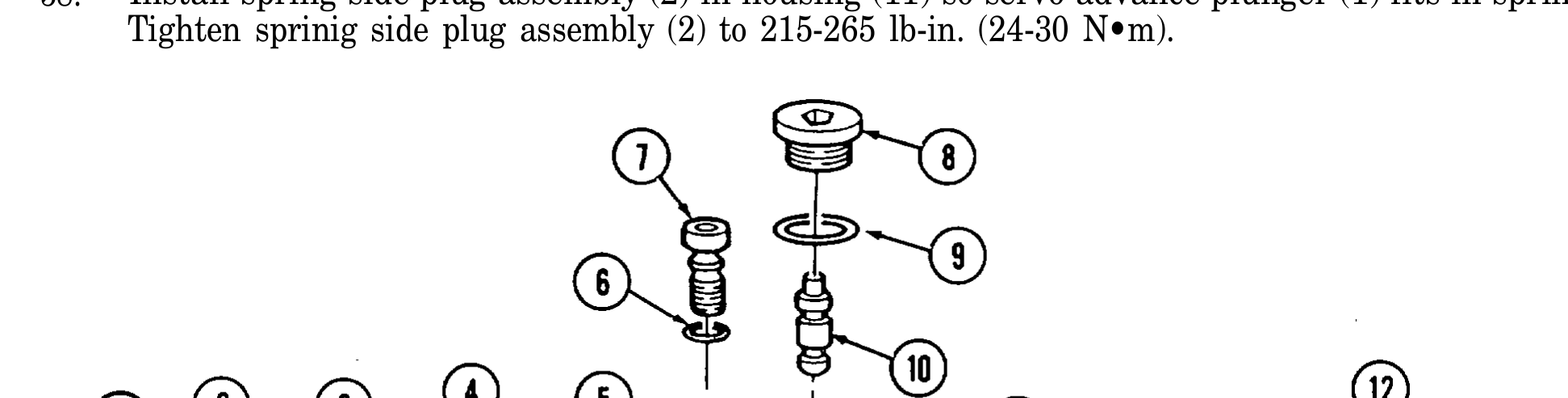
57. Install servo advance plunger (1) and O-ring (3) on spring side plug (2).
58. Install spring side plug assembly (2) in housing (11) so servo advance plunger (1) fits in spring (4). Tighten sprinig side plug assembly (2) to 215-265 lb-in. (24-30 N•m).
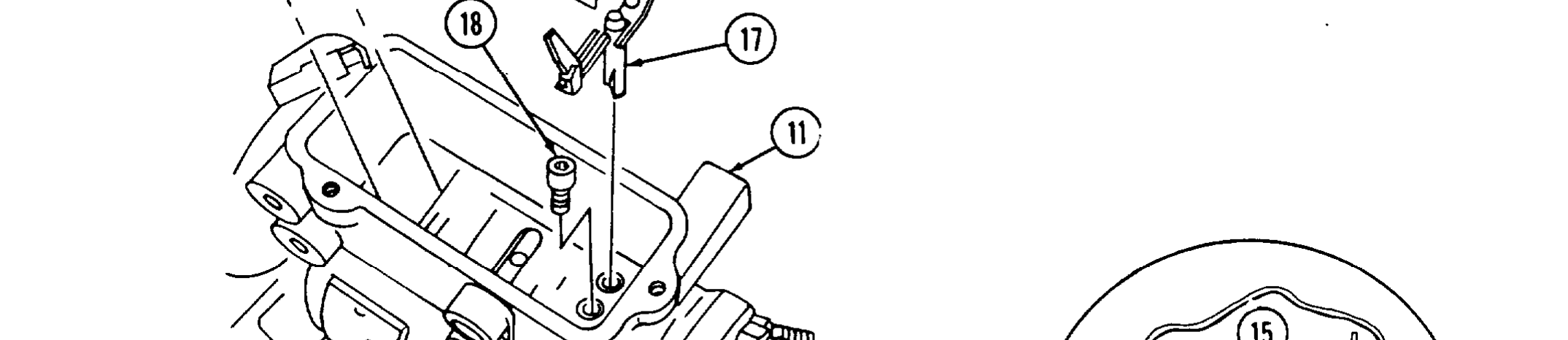
59. Rotate housing (11) and holding fixture 180°
60. Install vent wire screw (18). Tighten to 25-30 lb-in. (3 N•m) with 1/8-in. hex head driver.
61. Install metering valve assembly (17) in housing (11).
62. Connect linkage hook (15) to governor arm (20).
63. Install spring (19) on governor arm (20) and linkage hook (15).
64. Install governor arm (20) in housing (11) so that feet on governor arm (20) fit in slots in thrust sleeve (21).
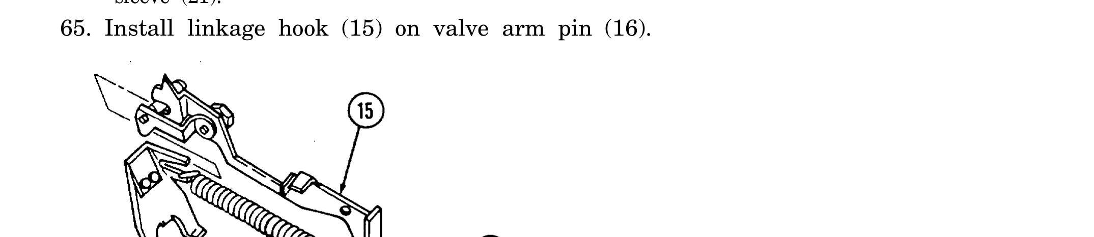
65. Install linkage hook (15) on valve arm pin (16).
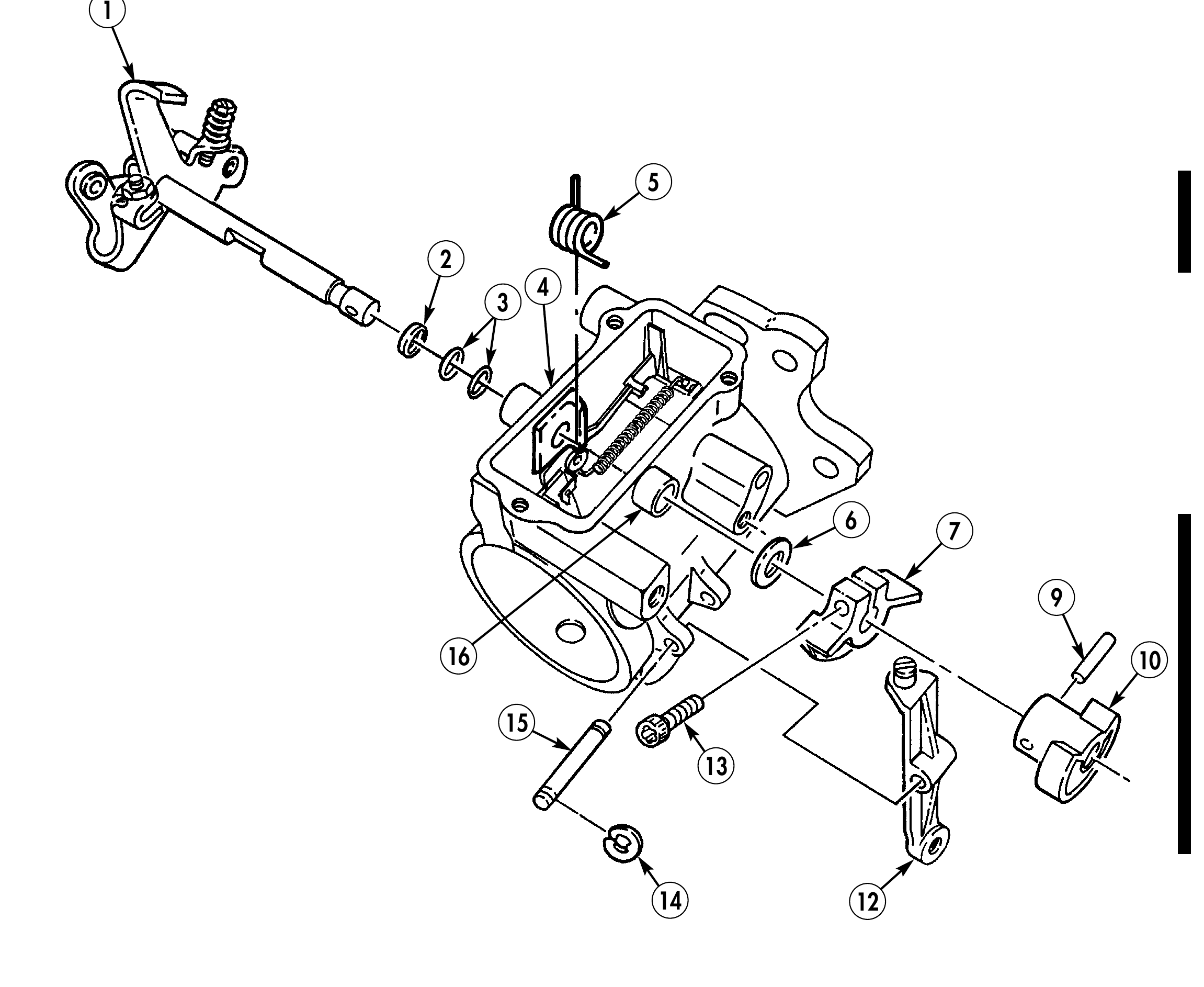
66. Install spacer (2) and two O-rings (3) on throttle shaft (1) and install throttle shaft (1) in housing (4).
67. Install spacer (2) and two O-rings (3) on throttle shaft (1). Position governor thrust spring (5) inside housing (4) and insert throttle shaft (1) through housing (4) and thrust spring (5).
68. Install mylar washer (6) and face cam (7) on throttle shaft (1) with screw (13). Finger tighten screw (13).
69. Install rocker lever (12) on housing (4) with rocker lever pin (15) and two retaining clips (14).
70. Put 0.005-in. (0.127 mm) feeler gauge between throttle shaft mylar washer (6) and housing boss (16).
71. Put throttle shaft (1) in idle position. Squeeze throttle shaft (1) and face cam (7) tightly toward each other and rotate face cam (7) so lower roller rests approximately in middle of low idle step. Tighten screw (13) to 30 lb-in. (3 N•m) with Torx drive and remove feeler gauge.
72. Align holes in kickdown cam (10) and throttle shaft (1).
73. Install kickdown cam (10) on throttle shaft (1) with retaining pin (9).
74. Deleted.
6 7
16 10
14 12
75. Install idle spring (1) on pushrod (2).
76. With throttle shaft (8) in wide open position, install min-max governor (4) on notch of throttle shaft (8). Rotate throttle shaft (8) to low idle position and lower min-max governor (4) into housing (5).
77. Insert inner governor spring (9) into pushrod (2).
78. With throttle shaft (8) in wide open position, install min-max governor (4) on notch of throttle shaft (8) and position tang (12) of thrust spring (11) in groove on throttle block (3). Rotate throttle shaft (8) to low idle position and lower min-max governor (4) into housing (5).
79. Hook tang (10) of thrust spring (11) in groove (13) of housing (5).
80. Install nut (17) and seal (16) on guide stud (7). Install guide stud (7) in housing (5) between metering valve arm (15) and spring (14) and into min-max governor (4). Tighten guide stud (7) to 80-90 lb-in. (9-10 N•m) using 1/4-in. hex head driver.
81. Install cap (18) on guide stud (7).
82. Install guide stud (7) and washer (6) in housing (5) between metering valve arm (15) and spring (14) and into min-max governor (4). Tighten guide stud (7) to 80-90 lb-in. (9-10 N•m) using 1/4-in. hex head driver.
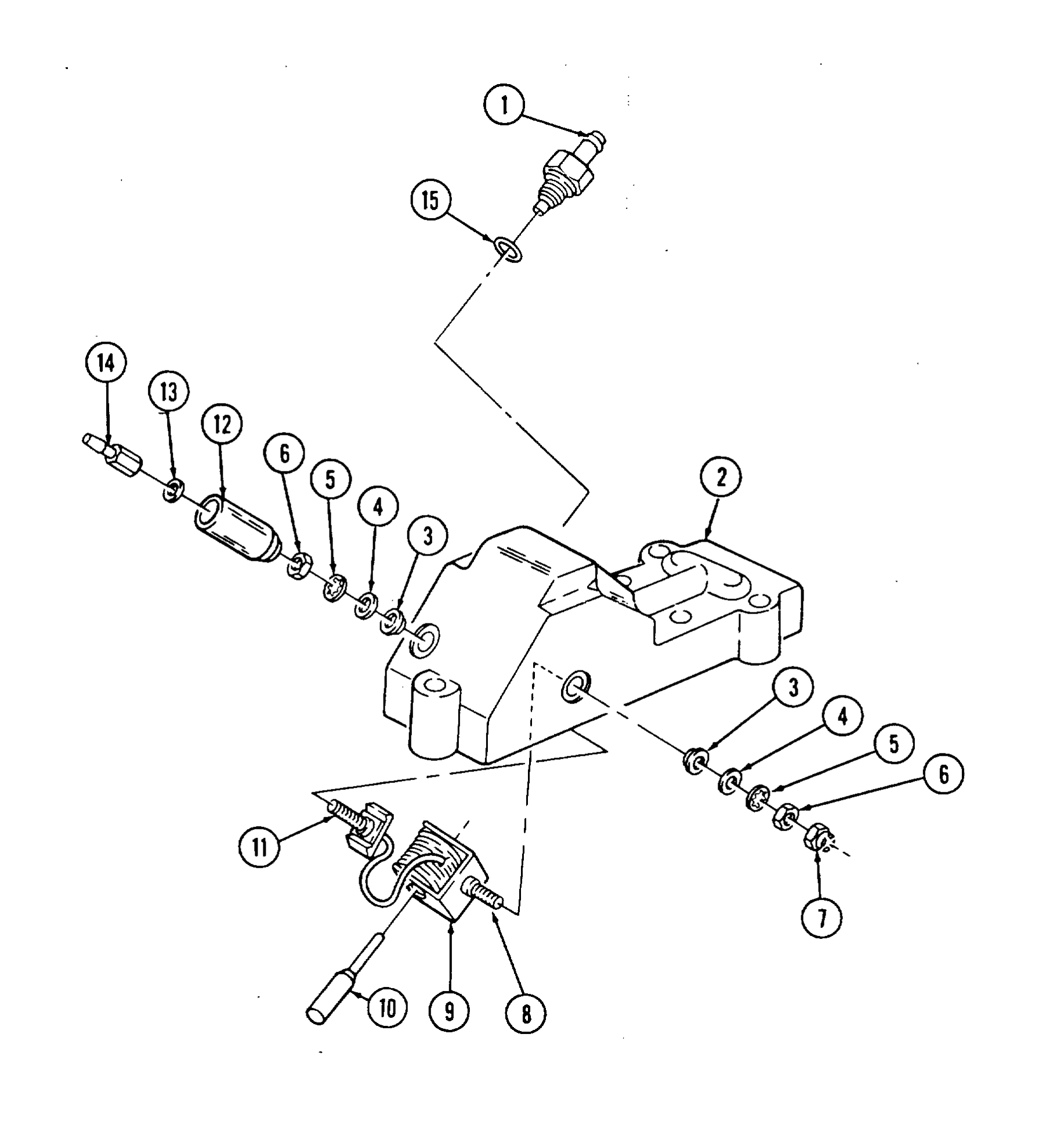
83. Install O-ring (15) and check valve (1) in cover (2).
84. Install plunger (10) in cold start advance solenoid (9) and stud (11) in hole in rear of cover (2).
85. Install cold start advance solenoid (9) in cover (2) so small tip of plunger (10) fits in port of check valve (1) and stud (8) fits through hole inside of cover (2).
86. Install fiber washer (3), washer (4), lockwasher (5), nut (6), and locknut (7) on stud (8).
87. Install fiber washer (3), washer (4), lockwasher (5), and nut (6) on stud (11).
88. Install shell (12), washer (13), and terminal (14) on stud (11).
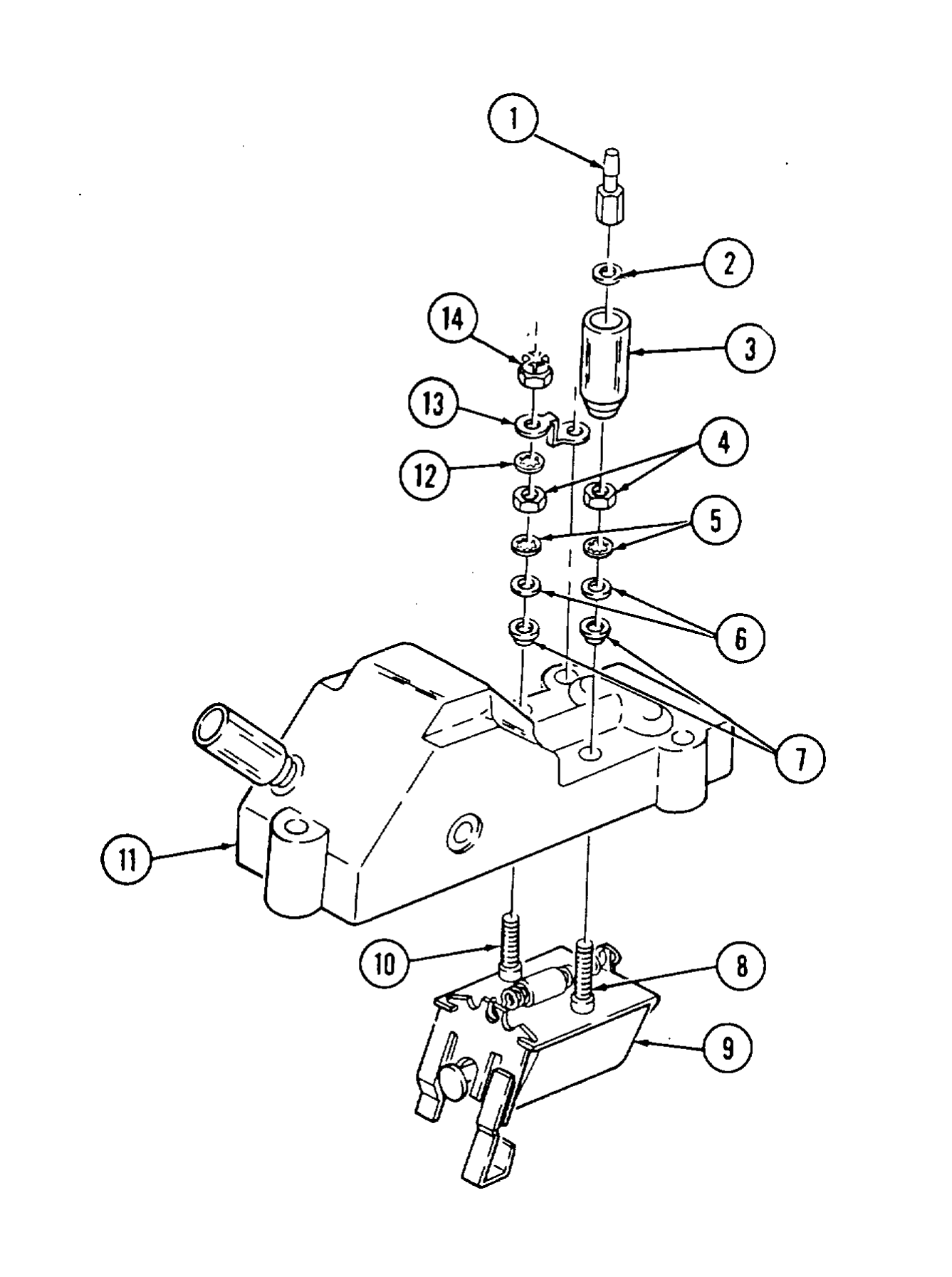
89. Install electrical shutoff solenoid (9) in cover (11).
90. Install fiber washer (7), washer (6), lockwasher (5), nut (4), lockwasher (12), ground strap (13) and locknut (14) on stud (10).
91. Install fiber washer (7), washer (6), lockwasher (5), and nut (4) on stud (8).
92. Install shell (3), washer (2), and terminal (1) on stud (8).
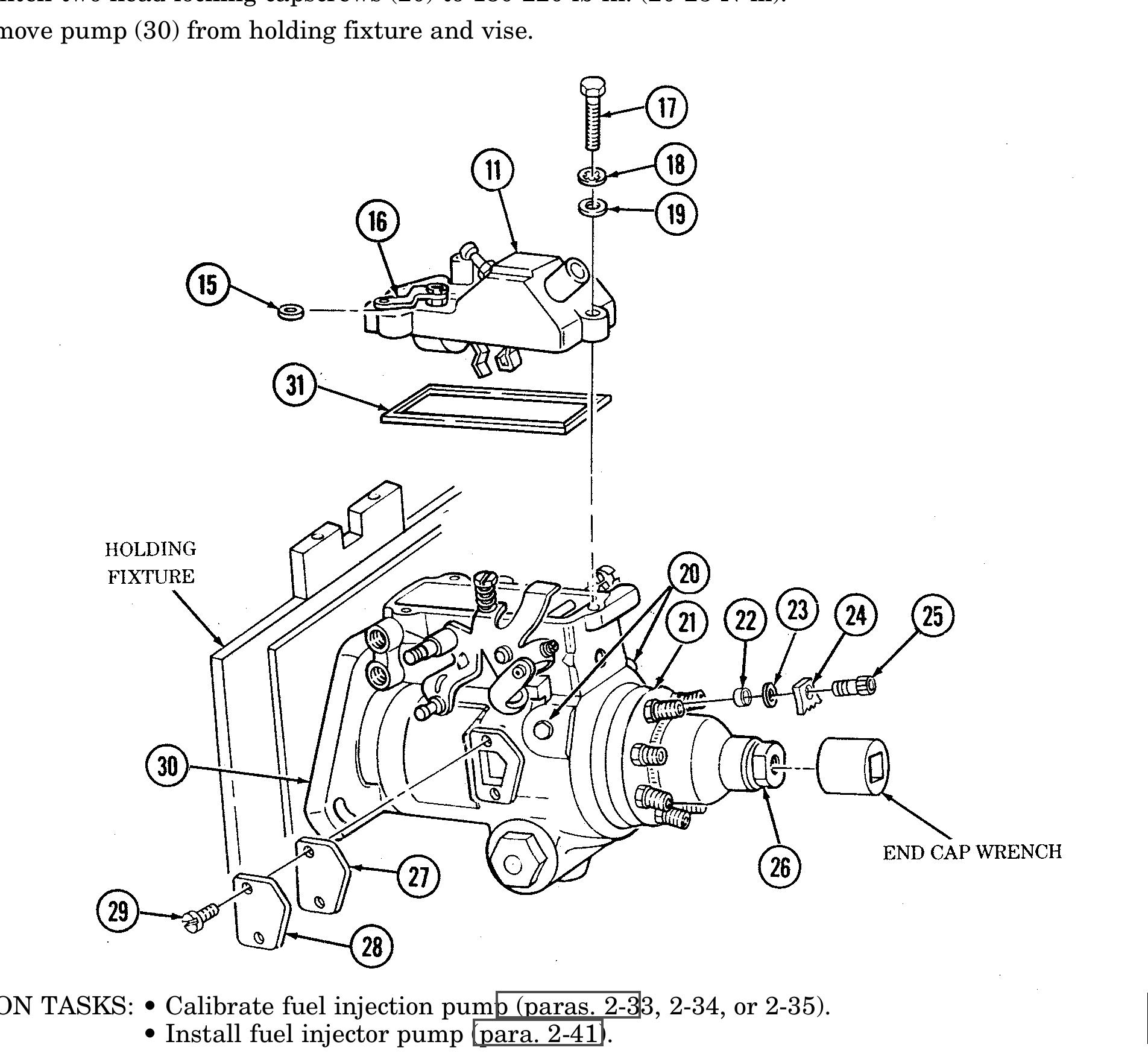
93. Install washer (15) between ground strap (16) and cover (11).
When installing cover on housing, cover must be positioned on housing ahead of threaded holes and slid rearward to align holes in cover with threaded holes in housing. Incorrect installation of cover may cause pump to malfunction.
94. Install gasket (31) and cover (11) on housing (30) and secure with three screws (17), lock- washers (18), and washers (19). Tighten screws (17) to 35-45 lb-in. (4-5 N•m).
95. Install timing cover (28) and gasket (27) on housing (30) and secure with two screws (29).
96. Using end cap wrench, tighten end cap (26) to 30-37 lb-ft (41-50 N•m).
97. Install transfer pump end cap locking screw (25), plate (24), flat washer (23), and rubber washer (22) in hydraulic head (21). Tighten screw (25) to 70-80 lb-in. (8-9 N•m) using 5/32-in. hex head driver.
98. Tighten two head locking capscrews (20) to 180-220 lb-in. (20-25 N•m).
99. Remove pump (30) from holding fixture and vise.
FOLLOW-ON TASKS: • Calibrate fuel injection pump (paras. 2-33, 2-34, or 2-35). • Install fuel injector pump (para. 2-41).