2-27. Oil Pump Repair
TM 9-2815-237-34 · Chapter 2 — Engine Maintenance
This task covers:
a. Disassembly c. Inspection
b. Cleaning d. Assembly
INITIAL SETUP:
     Tools                                                 Equipment Condition
       General mechanic’s tool kit:                          Engine disassembled into subassemblies
        automotive (Appendix E, Item 1)                      (para. 2-15).
       Hammer, soft head (Appendix E, Item 30)
     Materials/Parts
       Lubricating oil, OE/HDO (Appendix B,
       Item 13)
     Manual References
      TM 9-2815-237-34P

a. Disassembly

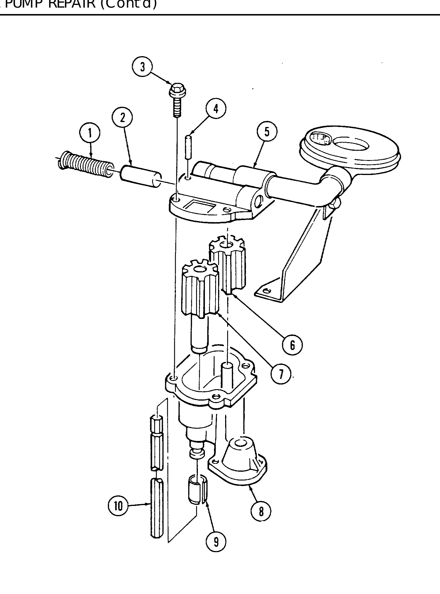
 1. Remove shaft extension (10) and coupling (9) from pump body (8).
 2. Remove four capscrews (3) and pump cover (5) from pump body (8).
 3. Mark drive gear (7) and idler gear (6) for assembly and remove.
 4. Remove retaining pin (4), regulator spring (l), and pressure regulator valve (2).

b. Cleaning

 Clean all components in accordance with para. 2-9.
c. Inspection

                                                       NOTE
                       ● For general inspection instructions, refer to para. 2-10.

                       ● Pump body, pump cover, and pump gears are not serviced

                          separately. If any of these parts require replacement, replace
                          entire oil pump.
 1. Inspect pump body (8) and pump cover (5) for damage. Replace oil pump if damaged.
 2. Inspect drive gear (7) and idler gear (6) for damage. Replace oil pump if damaged.
 3. Inspect regulator valve (2) for scoring or nicks. Replace if scored or nicked.
 4. Inspect regulator spring (1) for damage. Replace if damaged.
 5. Inspect shaft extension (10) and coupling (9) for damage. Replace if damaged.
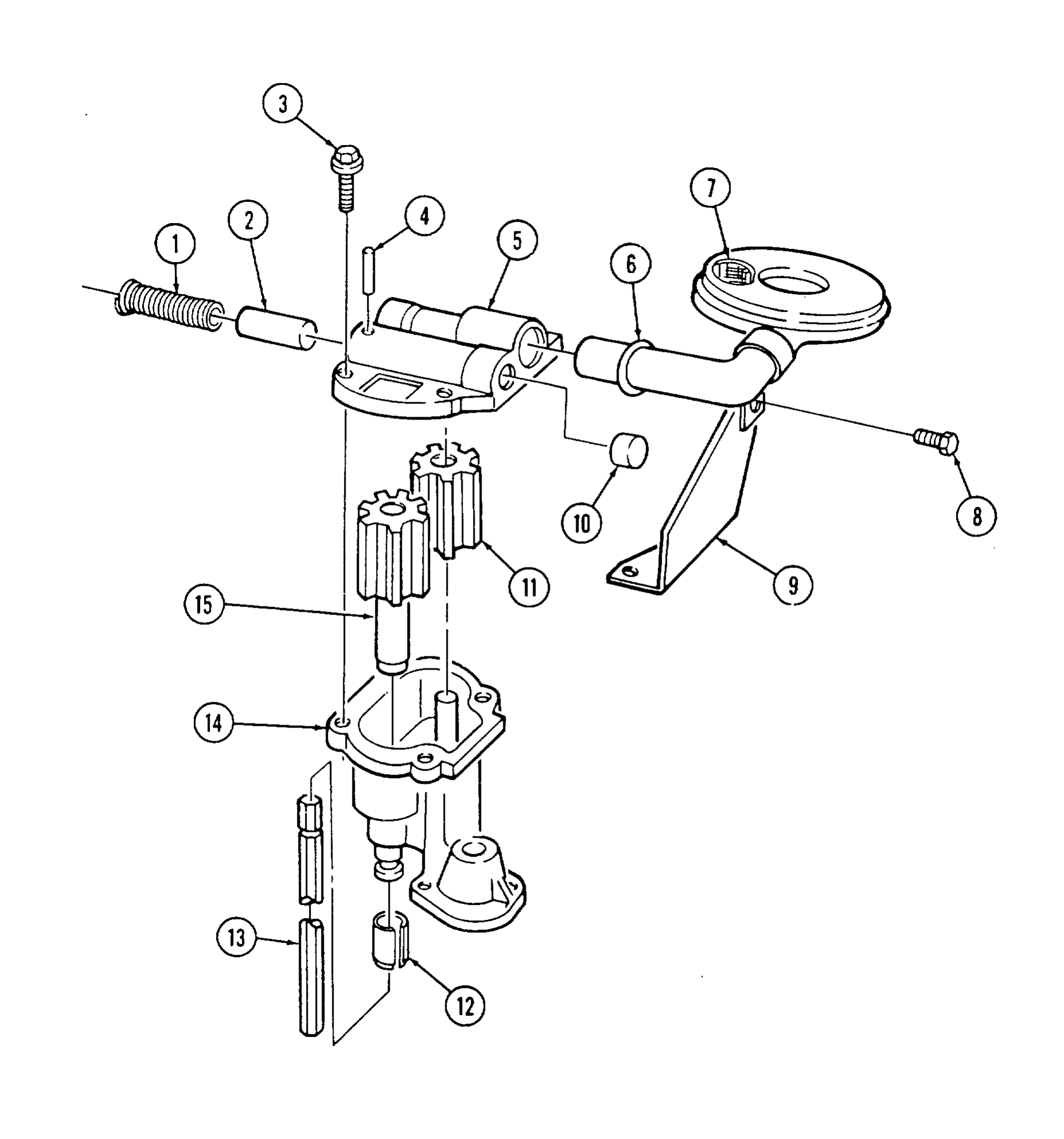
6. Inspect oil screen (7) for damage or blockage. If blocked or damaged, perform steps 8 through 12; if not, go to next step.
7. Inspect pickup tube bracket (9) for damage. If damaged, perform steps 8 and 12; if not, go to step 13.
8. Remove capscrew (8) and pickup tube bracket (9) from oil screen (7).
9. Place pump cover (5) in soft-jawed vise.
10. Using soft-head hammer, remove oil screen (7) from pump cover (5).
11. Using soft-head hammer, install oil screen (7) in pump cover (5) until bead (6) seats on pump cover (5).
12. Install pickup tube bracket (9) on oil screen (7) and install capscrew (8). Finger tighten capscrew (8).
13. Inspect regulator valve plug (10) for damage. Replace if damaged.
d. Assembly
1. Install regulator valve (2) and regulator spring (1) in pump cover (5) with retaining pin (4).
2. Install drive gear (15) and idler gear (11) into pump body (14) and aline reference marks. 3, Apply small amount of OE/HDO into pump body (14).
4. Install pump cover (5) on pump body (14) with four capscrews (3). Tighten capscrews (3) to 120 lb-in. (14 Nžm).
5. Install coupling (12) and shaft extension (13) on end of drive gear (15).