2-21. Cylinder Head and Valve Repair
TM 9-2815-237-34 · Chapter 2 — Engine Maintenance
This task covers:
a. Disassembly d. Refacing Valves
b. Cleaning e. Grinding Valve Seats
c. Inspection f. Assembly
INITIAL SETUP
      Tools                                              Materials/Parts
       General mechanic’s tool kit:                        Sixteen valve seals (Appendix D, Item 47)
        automotive (Appendix E, Item 1)                    Water jacket cover gasket (Appendix D, Item 20)
       Valve spring compressor                             Lubricating oil OE/HDO (Appendix B, Item 13)
        (Appendix E, Item 22)                              Pipe sealing compound (Appendix B, Item 17)
       Bench grinder (Appendix E, Item 23)
       Rotary wheel wire brush                           Manual References
        (Appendix E, Item 24)                              TM 9-2815-237-34P
       Electric drill (Appendix E, Item 25)
       Rotary end wire brush (Appendix E, Item 26)       Equipment Condition
       Valve spring tester (Appendix E, Item 27)           Engine disassembled into subassemblies
       Straightedge (Appendix E, Item 15)                  (para. 2-15).
       Feeler gauge (Appendix E, Item 13)
       Dial indicator (Appendix E, Item 10)
       Valve face grinding machine
        (Appendix E, Item 28)
       Valve seat grinding kit (Appendix E, Item 29)

                                                   NOTE
                  The cylinder head and valve repair procedures for 6.5L engines, 1990 and
                  above 6.2L engines and previous model engines are basically the same.
                  Any differences in procedures are noted. Refer to engine decal model
                  number on left rocker arm cover before ordering replacement parts.
a. Disassembly

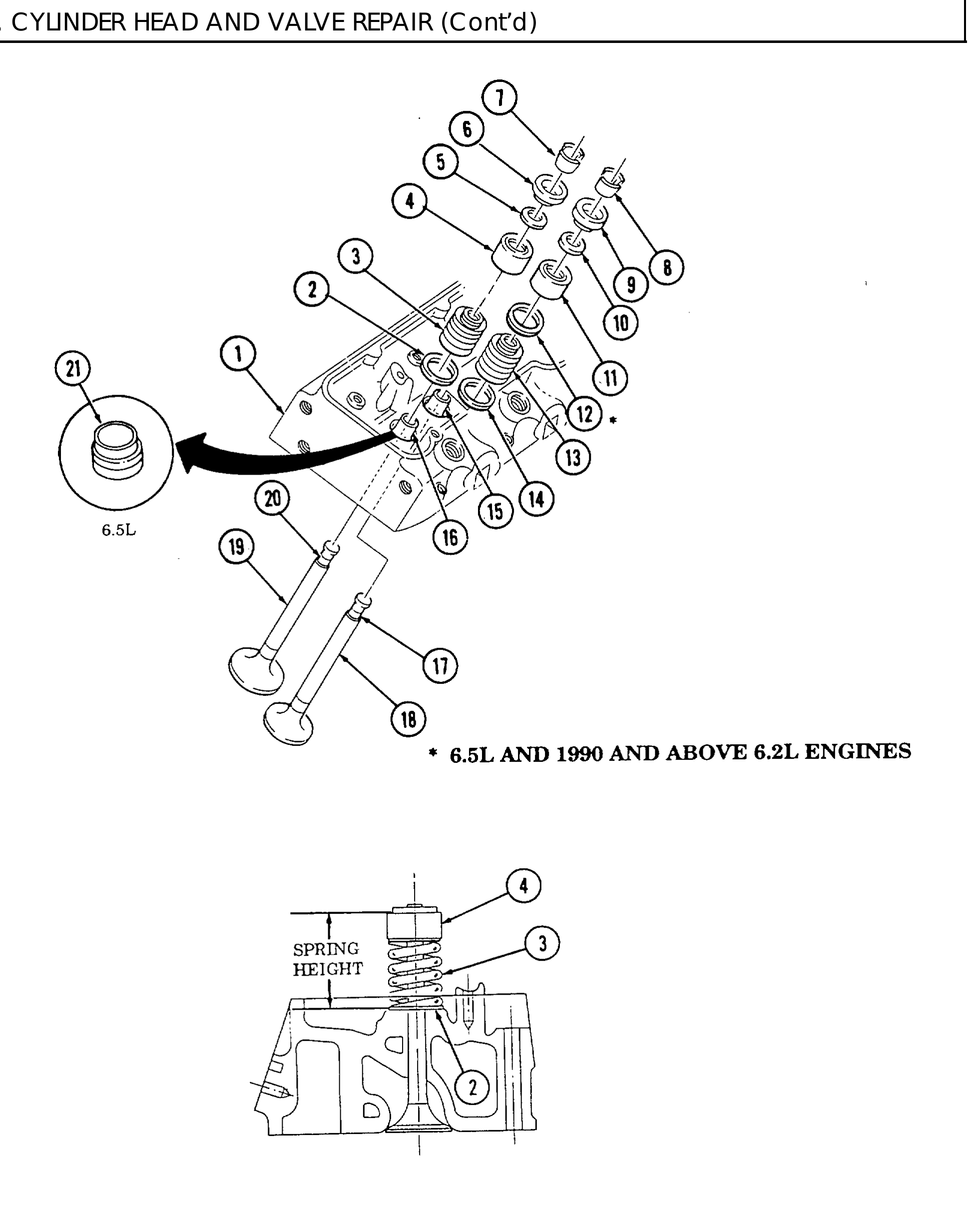
 1.     Using valve spring compressor, compress intake valve spring (3) and remove valve keys (7).
        Release valve spring compressor slowly.
 2.     Remove valve cap (6), shield (4), valve spring (3), valve spring shim (2), and valve seal (5) from
        intake valve (16). Discard valve seal (5).
                                                     NOTE
                    Valves must be installed in the same location they were removed from.
                    As each valve is removed, place on numbered board or stand.
 3.     Remove intake valve (16) from cylinder head (1).
 4,     Repeat steps 1 through 3 for remaining intake valves.
 5.     Using valve spring compressor, compress exhaust valve spring (13) and remove valve keys (8).
        Release valve spring compressor slowly.
                                                     NOTE
                     ● Valve caps on exhaust valves are rotaters.

                     ● Perform step 6 for 6.5L and 1990 and above 6.2L engines only. 6.5L

                       engine has another seal as indicated in step 6.
 6.     Remove valve cap (9), shield (11), valve stem seal (12), valve spring (13), valve spring shim (14),
        seal (17), and valve seal (10) from exhaust valve (15). Discard valve seal (10).
 7.     Remove valve cap (9), shield (11), valve spring (13), valve spring shim (14), and valve seal (10) from
        exhaust valve (15). Discard valve seal (10).
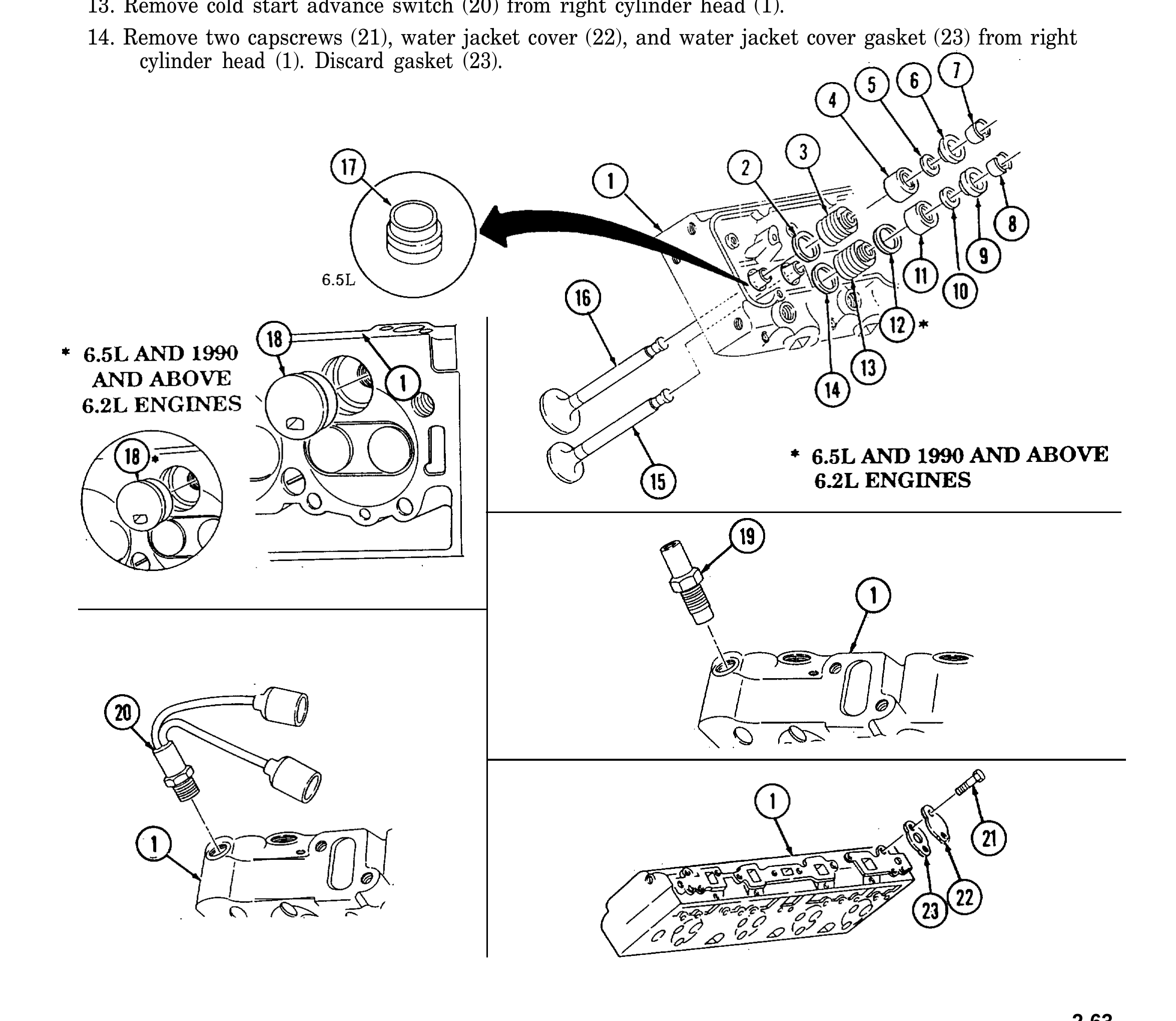
8. Remove exhaust valve (15) from cylinder head (1).
9. Repeat steps 5 through 8 for remaining exhaust valves.
10. Remove four precombustion chambers (18) from cylinder head (1).
11. Repeat steps 1 through 10 for opposite cylinder head.
12. Remove engine temperature sending unit (19) from left cylinder head (1)
13. Remove cold start advance switch (20) from right cylinder head (1).
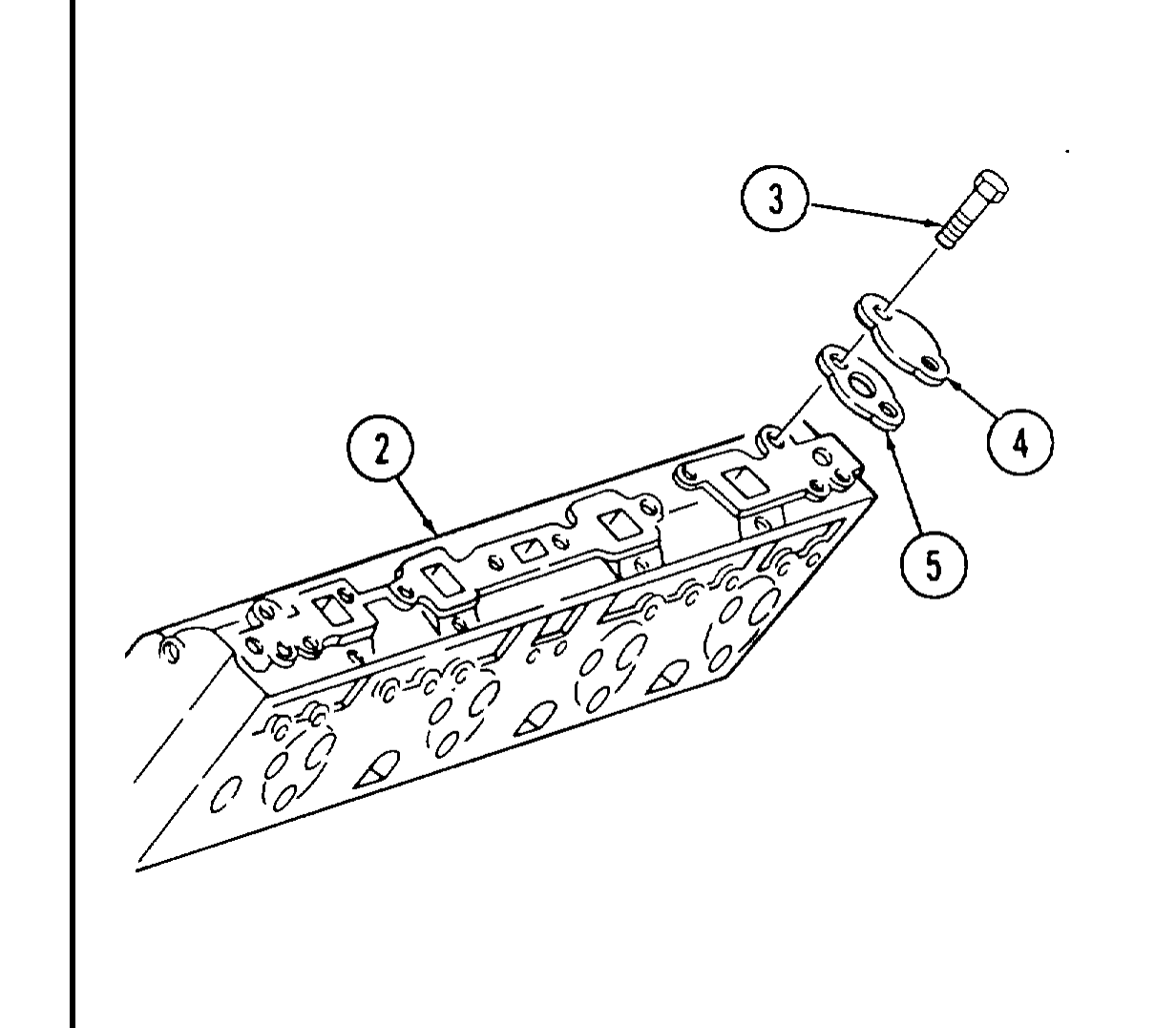
14. Remove two capscrews (21), water jacket cover (22), and water jacket cover gasket (23) from right cylinder head (1). Discard gasket (23).
b. Cleaning
1. Using bench grinder and rotary wheel wire brush, clean all valve stems (2) and valve heads (3).
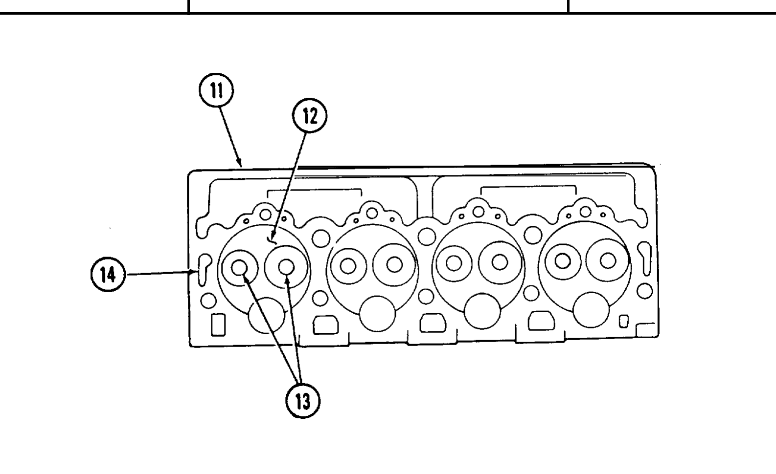
2. Using drill motor and rotary end wire brush, clean all combustion chambers ( 12) and intake and exhaust ports (13).
3. Refer to para. 2-9 for additional cleaning information.
4. Repeat steps 1 through 3 for opposite cylinder head.
c. Inspection
1. Inspect valves (1) for cracks, scoring, galling, and burned heads (3). Replace valves (1) if cracked, scored, galled, or if heads (3) are burned.
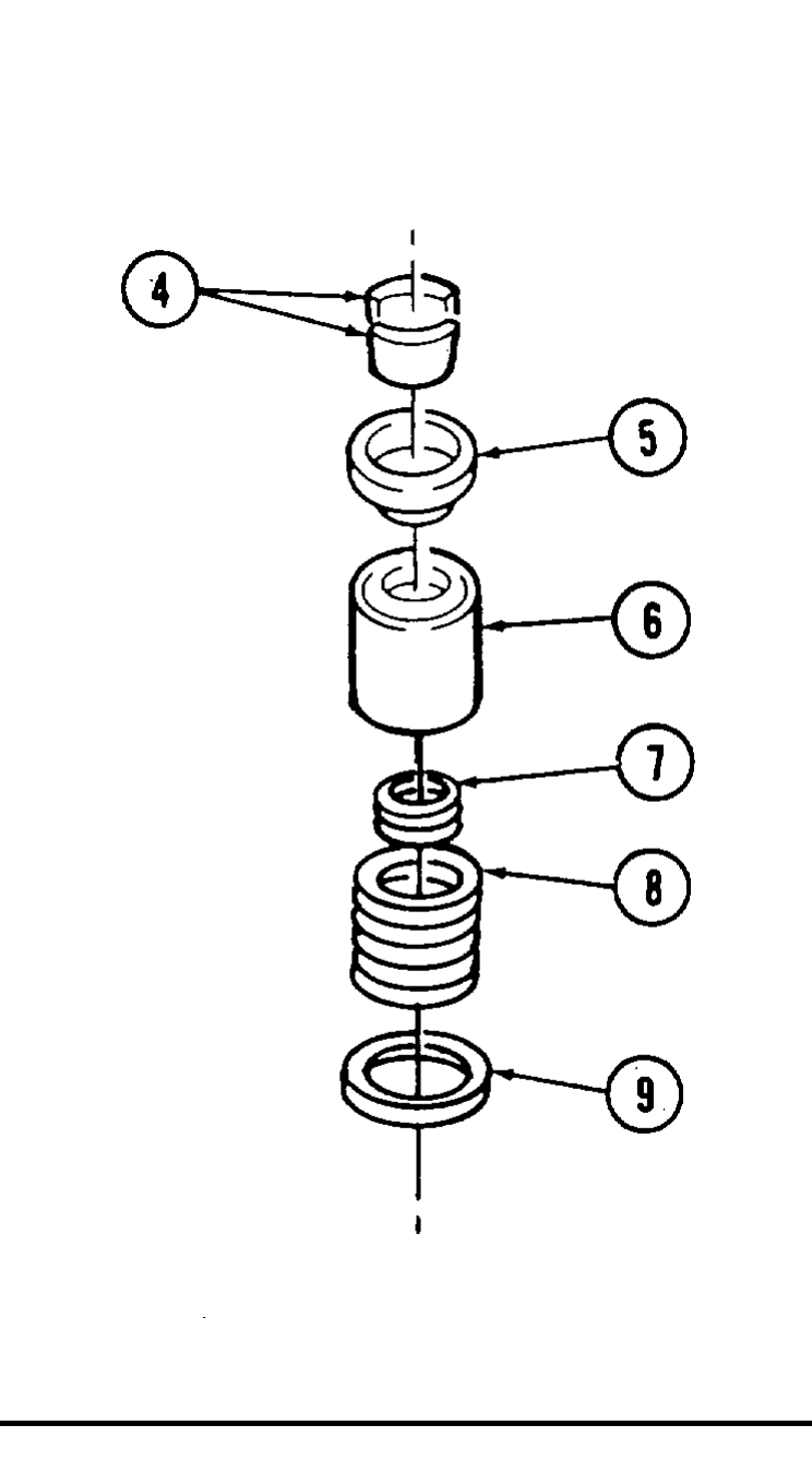
2. Inspect valve springs (8) and dampers (7) for damage. Replace valve spring (8) if either are damaged.
3. Inspect valve caps (5), shields (6), valve spring shims (9), and valve keys (4) for damage. Replace if damaged.
4. Remove dampers (7) from valve springs (8). Using valve spring tester, compress valve spring (8) to 1-13/16 in. (46 mm). If pressure is less than 70 lb (311 N), replace valve spring (8). Compress valve spring (8) to 1-25/64 in. (35 mm). If pressure is less than 220 lb (978 N), replace valve spring (8). Test remaining springs in same manner. Install dampers (7) into springs (8).
5. Inspect cylinder head (11) for cracks in valve ports (13) or combustion chambers (12) and external cracks to the coolant chamber (14). Replace cylinder head (11) if cracked.
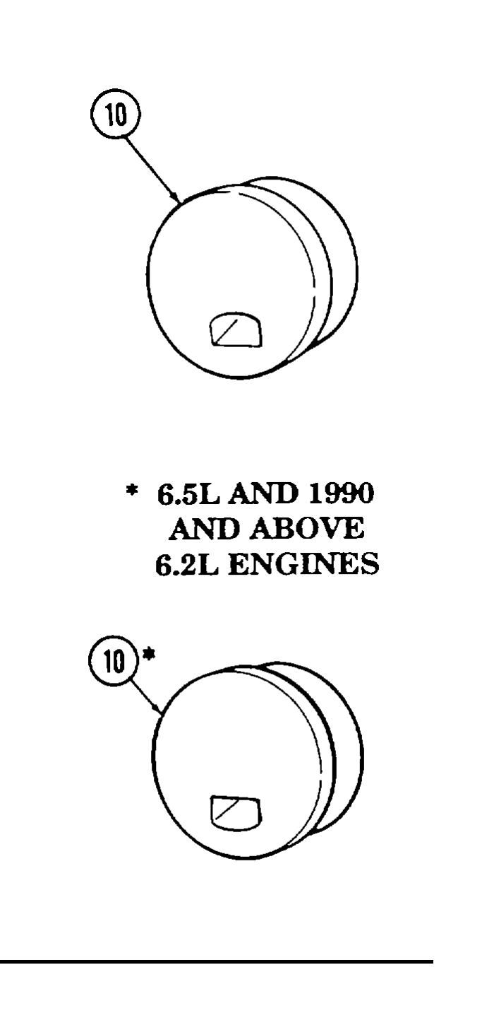
6. Inspect precombustion chambers (10) for cracks or damage. Replace if cracked or damaged.
7. Inspect cylinder head (11) mating surfaces for scratches or dents. Replace cylinder head (11) if scratched or dented deeper than 0.003 in. (0.076 mm).
8. Using a straight edge and feeler gauge, check flatness of cylinder head to block mating surface. Flatness of cylinder head (11) must not vary more than 0.002-in. (0.051 mm) in distance of 6 in. (15.2 cm), or more than 0.006 in. (0.152 mm) overall. Replace cylinder head (11) if flatness does not meet specifications.
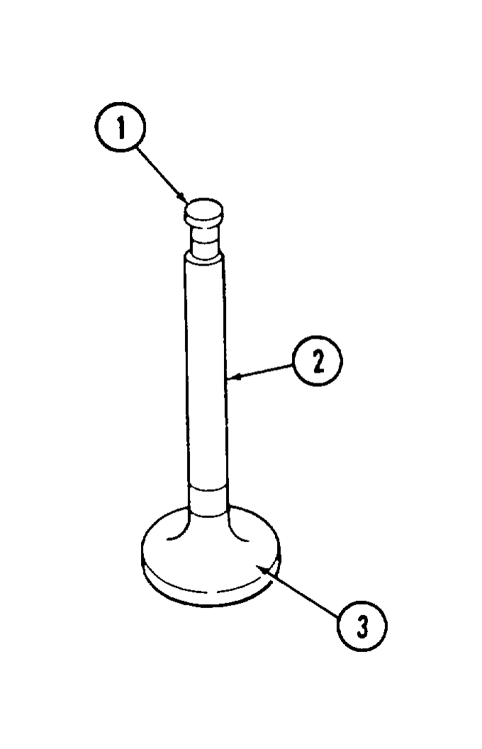
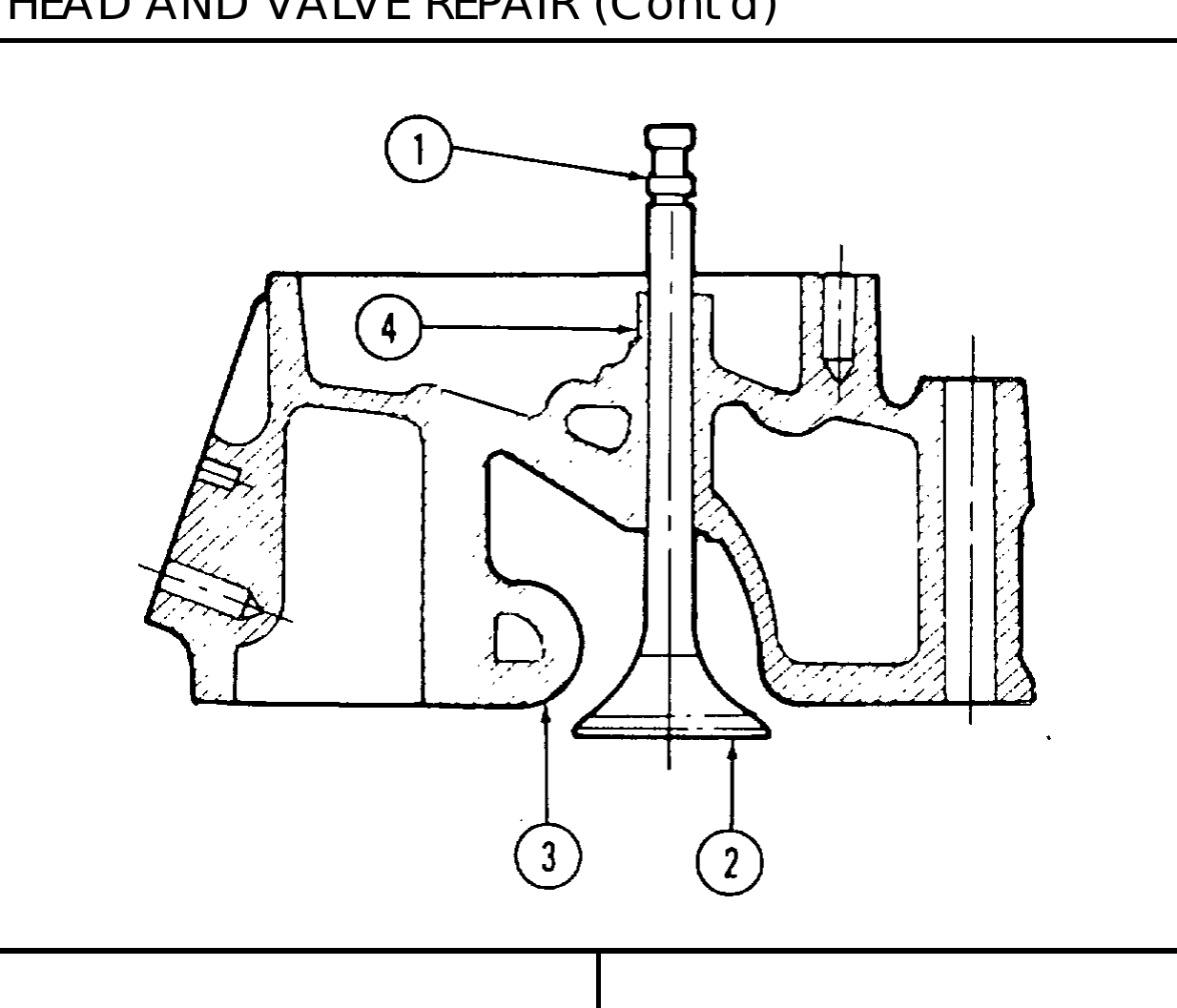
9. Install valve (2) in valve guide (4) from which it was removed.
(0.089 mm) and 0.0137 in. (0.349 mm) oversize stems. ● If valve stem clearance is more than 0.0027 in. (0.068 mm), valve
guide must be reamed to next size and oversized valve installed. If unable to produce clearance with oversize valve, replace cylinder head.
10. Using dial indicator, measure valve stem clearance. Dial indicator must contact valve stem (1) just above valve guide (4) and at a right angle to the valve stem (1). Drop valve (2) approximately 1/16 in. (1.6 mm) off valve seat (3) and move side-to-side when taking measurement.
11. Repeat steps 9 and 10 for remaining valves (2) and valve guides (4).
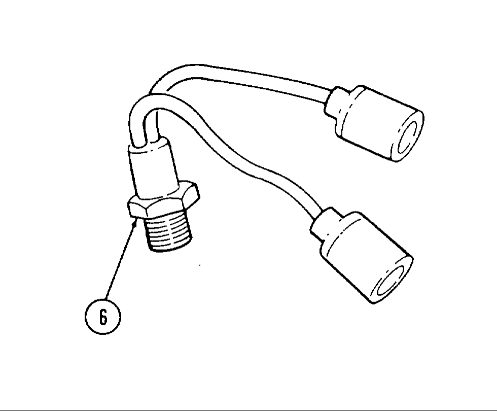
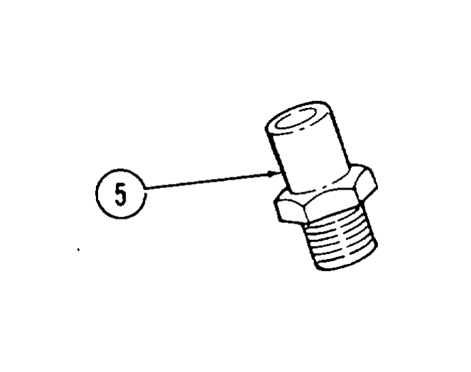
12. Inspect cold start advance switch (6) and engine temperature sending unit (5) for damage. Replace if damaged.
d. Refacing Valves
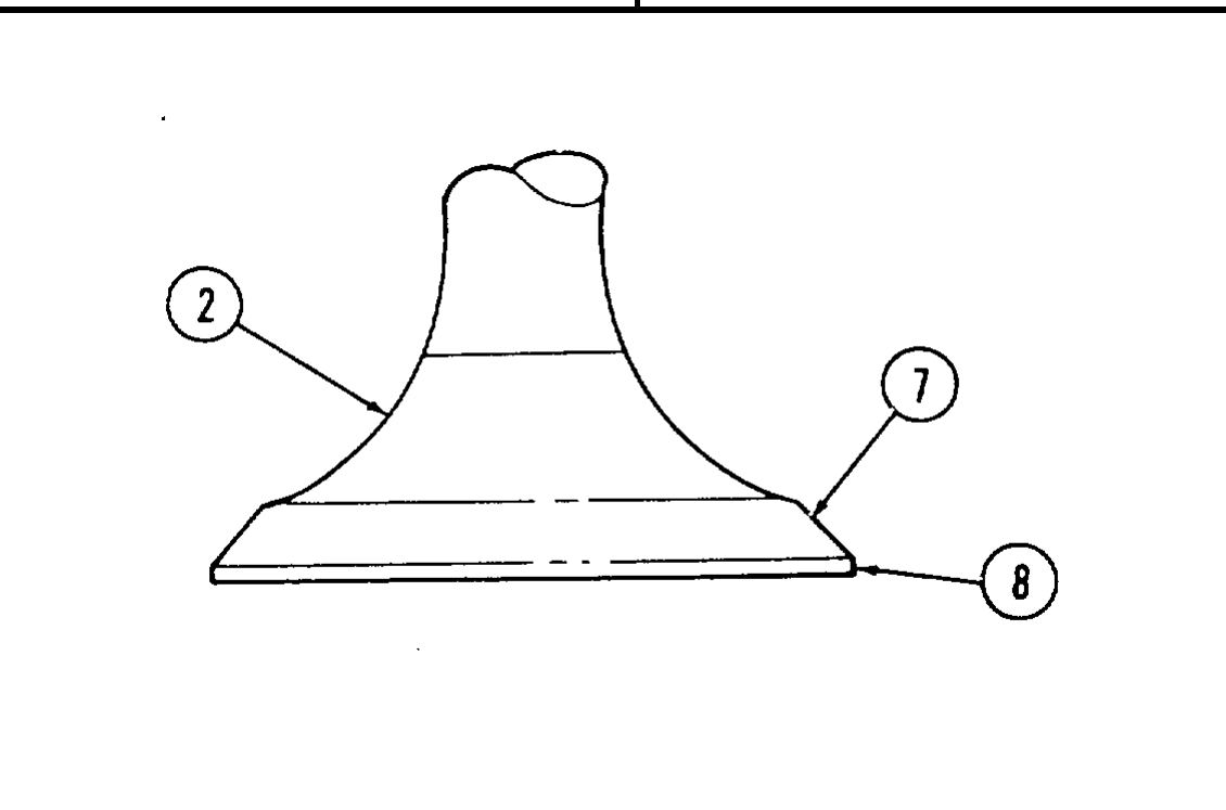
1. Using valve face grinding machine, grind valve face (7) on all valves (2) to 45”.
2. Maintain a minimum of 1/32 in. (0.80 mm) margin (8) on all valves (2). If margin falls below specifications, replace valve.
e. Grinding Valve Seats
1. Using valve seat grinding kit, grind all valve seats (3) to 46°.
2. Measure width of intake valve seats (3). Valve seats (3) must not be wider than 1/16 in. (1.53 mm).
3. Measure width of exhaust valve seats (3). Valve seats (3) must not be wider than 3/32 in. (2.36 mm).
f. Assembly
1. Apply OE/HDO to exhaust valve (18) and install valve (18) in valve guide (15) from which it was removed.
● Perform step 2 for 6.5L engines and 1990 and above
6.2L engines. Perform step 3 for previous model 6.2L engines.
2. Install seal (21), valve spring shim (14), valve spring (13), valve stem seal (12), shield (11), and valve cap (9) on exhaust valve (18).
3. Install valve spring shim (14), valve spring (13), shield (11), and valve cap (9) on exhaust valve (12).
4. Using spring compressor, compress valve spring (13) and install valve seal (10) in groove (17) in exhaust valve (18) and install valve keys (8). Slowly release spring compressor.
5. Apply OE/HDO to intake valve (19) and install valve (19) in valve guide (16) from which it was removed.
6. Install valve spring shim (2), valve spring (3), shield (4), and valve cap (6) to intake valve (19).
7. Using valve spring compressor, compress valve spring (3) and install valve seal (5) in groove (20) in intake valve (19) and install valve keys (7). Slowly release spring compressor.
8. Check installed height of valve springs (3) measuring from top of valve spring shim (2) to top of shield (4).
9. Spring height must be 1-13/16 in. (46 mm). If spring height is greater, remove valve spring (3) and add spring shim(s) (2) to bring spring height within specifications.
10. Repeat steps 1 through 9 for remaining valves and opposite cylinder head.
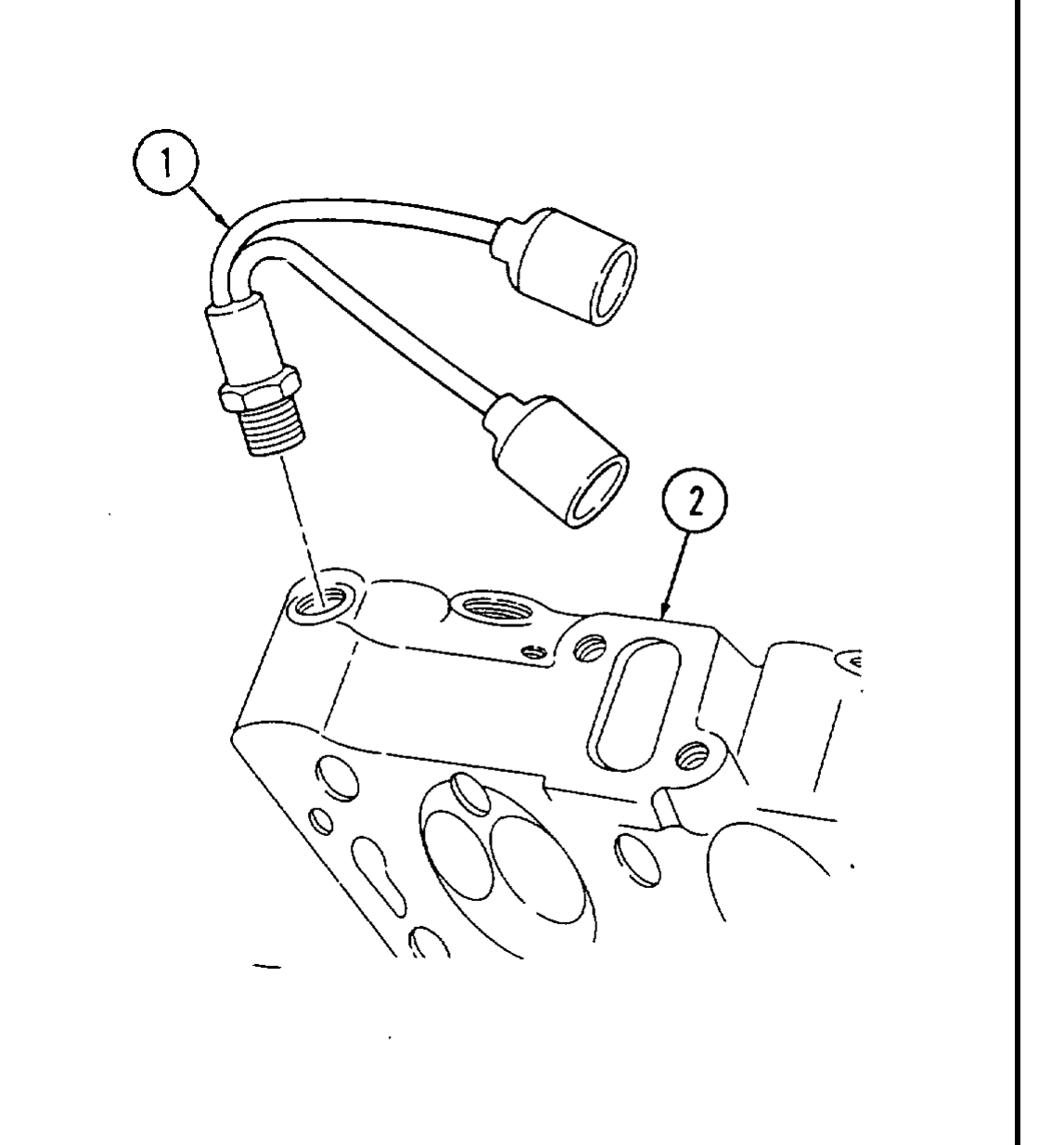
10. Apply pipe sealing compound to cold start advance switch (1) and install in right cylinder head (2).
11. Install water jacket cover gasket (5) and water jacket cover (4) on right cylinder head (2) and secure with two capscrews (3). Tighten capscrews (3) to 25-37 lb-ft (3450 Nžm).
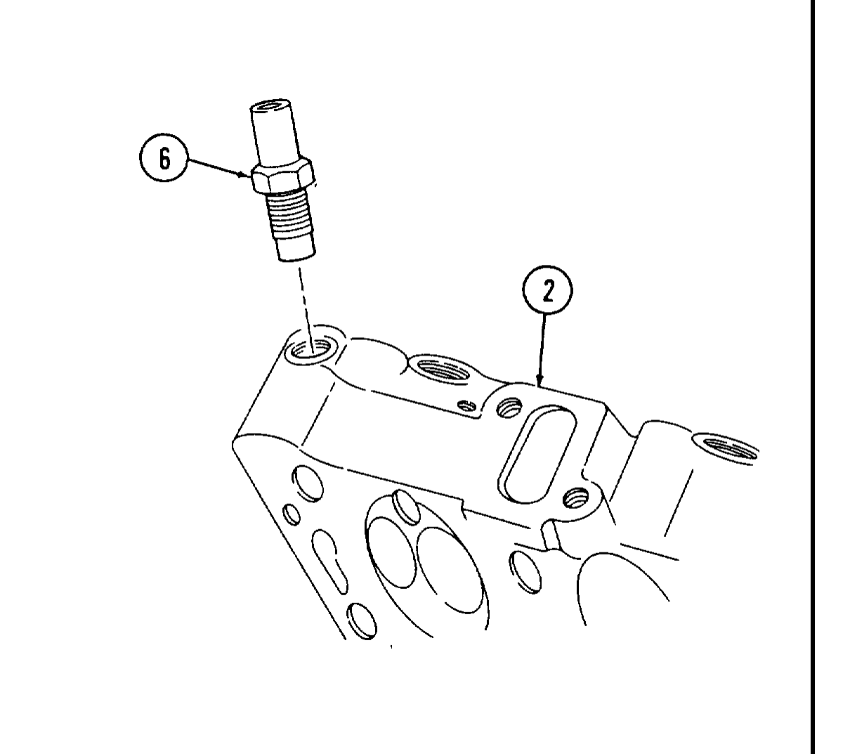
12. Apply pipe sealing compound to engine temperature sending unit (6) and install in left cylinder head (2).
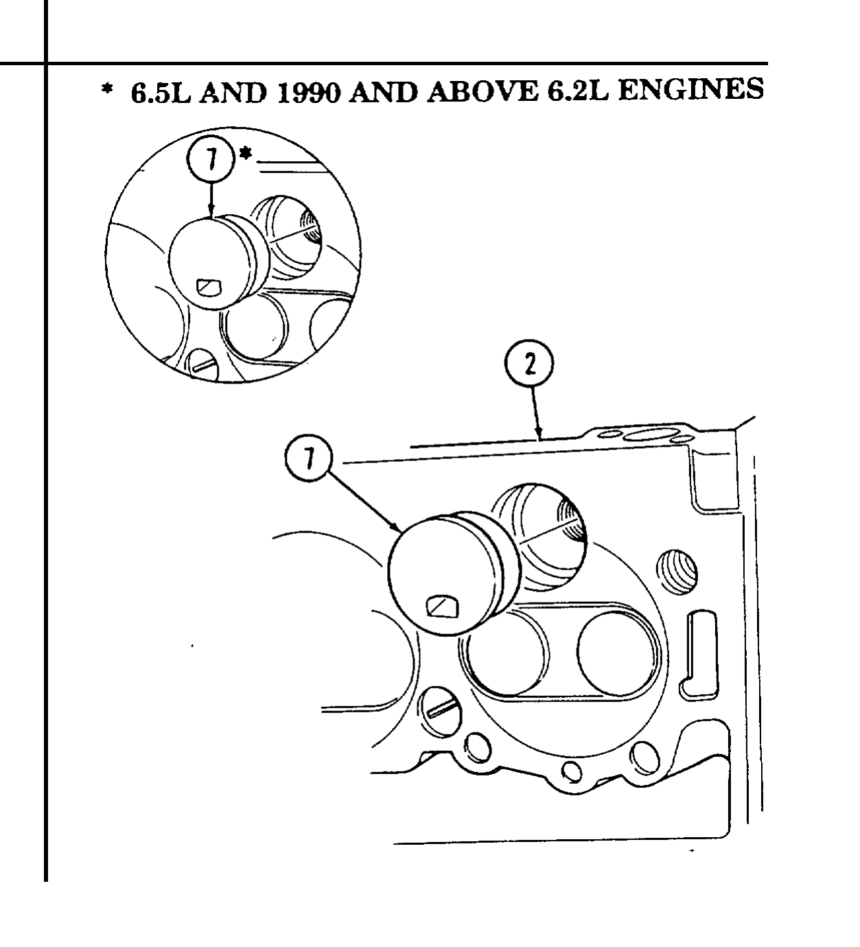
13. Install four precombustion chambers (7) in cylinder head (2) flush to +0.002 in. (0.050 mm).
14. Repeat step 13 for opposite cylinder head.