Tie Rod Replacement and Repair
TM 9-2320-363-34-1 · Chapter 5 — Front Axle Maintenance
This task covers: a. Removal b. Disassembly c. Cleaning d. Inspection e. Repair f. Assembly
                       g. Installation

Tools and Special Equipment:                         References:
Shop Equipment, SC 4910-95-CL-A31                    TM 9-2320-363-20
Tool Kit, SC 5180-90-CL-N05
Materials/Parts:
Pin, Cotter
Fitting, Lubrication

                                               NOTE
                              Procedure is the same for both tie rods.

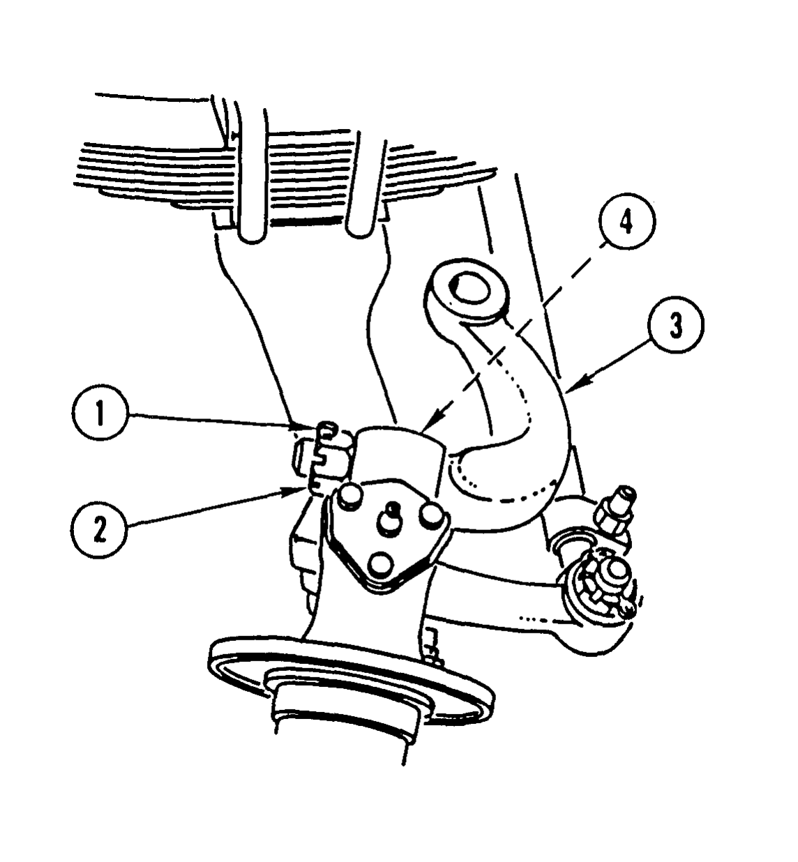
       REMOVE COTTER PIN (1), CASTELLATED NUT (2), AND TIE ROD (3). DISCARD COTTER PIN.
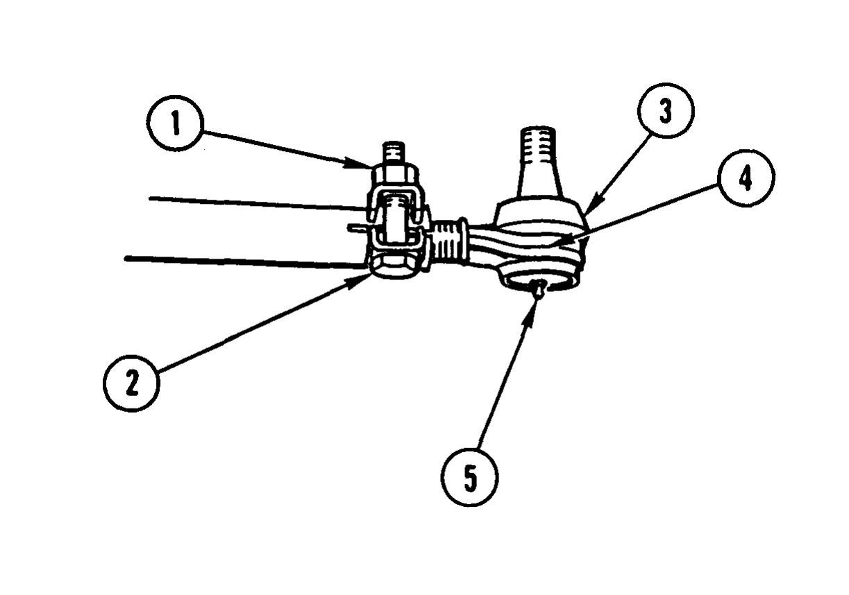
1. REMOVE LOCK NUT (1) AND CAPSCREW (2).
2. REMOVE DUST COVER (3).
Note number of turns necessary to remove tie rod end. Left tie rod end has left-hand threads. Right tie rod end has right-hand threads.
3. REMOVE TIE ROD END (4).
4. IF DAMAGED, REMOVE LUBRICATION FlTTlNG (5).
Use general cleaning methods to clean all parts (page 2-30).
Inspect all parts for wear or damage.
Repair of tie rod is the replacement of any worn or damaged parts.
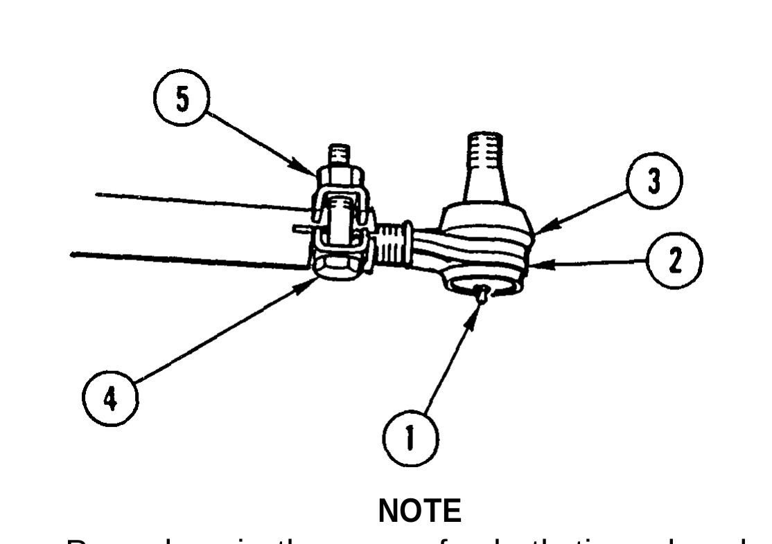
1. IF REMOVED, INSTALL NEW LUBRICATION FlTTING (1).
2. INSTALL TIE ROD END (2) NUMBER OF TURNS NOTED DURING DISASSEMBLY.
3. INSTALL DUST COVER (3).
4. INSTALL CAPSCREW (4) AND LOCK NUT (5). DO NOT TIGHTEN LOCK NUT.
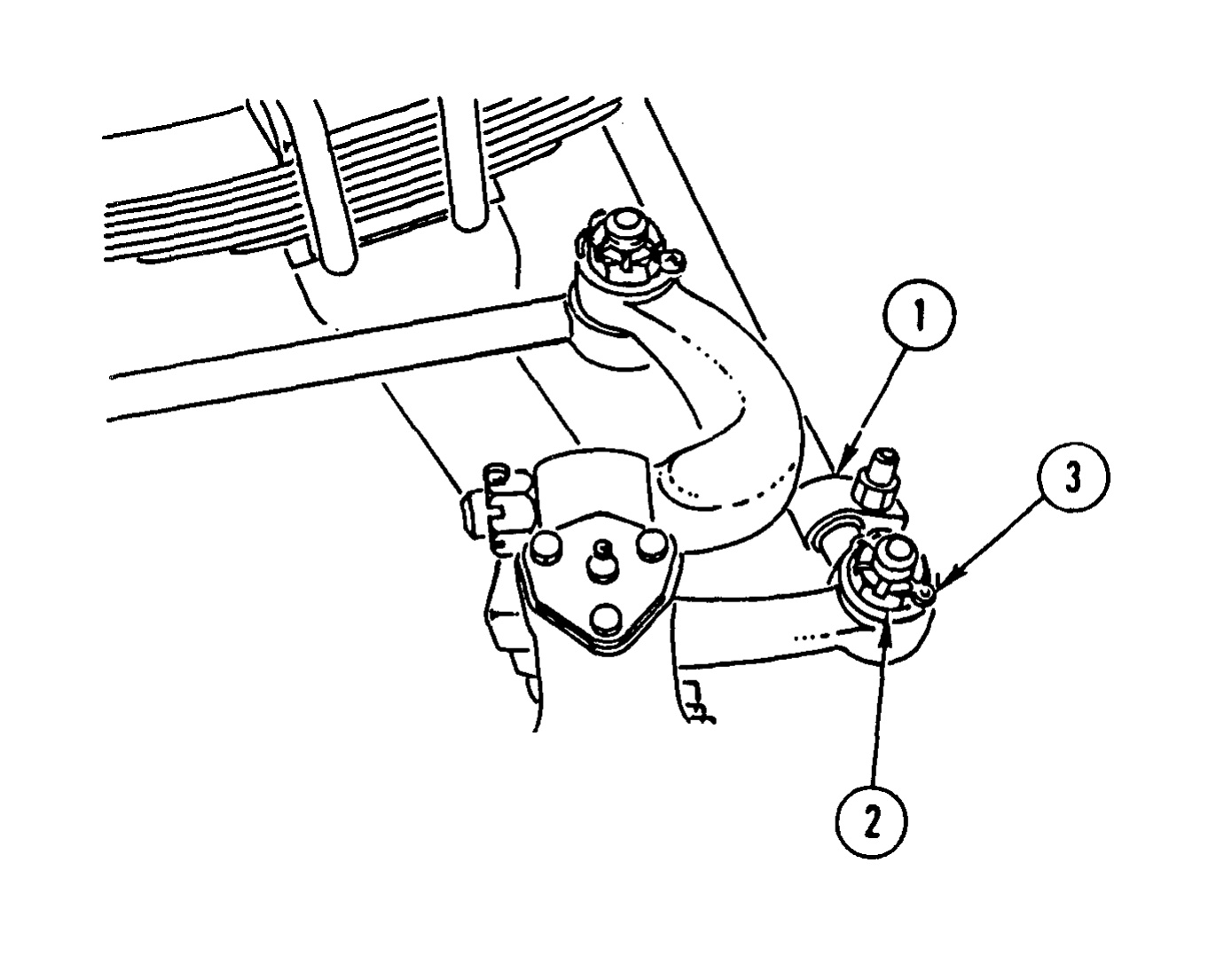
INSTALL TIE ROD (1), CASTELLATED NUT (2), AND NEW COTTER PIN (3). TIGHTEN CASTELLATED NUT TO 165-180 LB-FT (224-244 N.m).
Check front axle toe-in alinement (TM 9-2320-363-20).