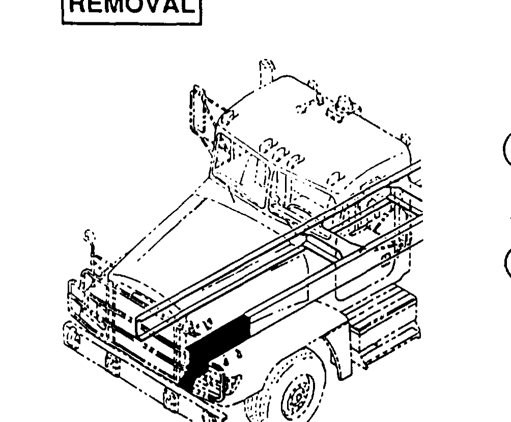
Steering Gear Replacement
TM 9-2320-363-34-1 · Chapter 7 — Steering Maintenance
This task covers: a. Removal b. Cleaning c. Inspection d. Installation
Tools and Special Equipment:                        Equipment Condition:
Shop Equipment, SC 4910-95-CL-A31                   Reference                Condition Description
Tool Kit, SC 5180-90-CL-N05
                                                    TM 9-2320-363-10         Vehicle Parked with
Materials/Parts:                                                             Wheels Pointed Straight
                                                                             Ahead
Nut, Lock
                                                    TM 9-2320-363-20         Drag Link Removed
Nut, Lock (2)             P/N 23-09901-114
                                                    General Safety Instructions:
Washer, Lock
Packing
                                                                     WARNING
Packing
                                                           Spilled power steering fluid is
                                                           very slippery. Wipe up any
Personnel Required: (2)
                                                           spilled fluid immediately.
References:                                                Failure to do so could result in
                                                           serious injury to personnel.

TM 9-2320-363-10
TM 9-2320-363-20
1. REMOVE PLUG (1) FROM STEERING GEAR (2) AND DRAIN POWER STEERING FLUID INTO SUITABLE CONTAINER.
2. INSTALL PLUG (1) IN STEERING GEAR (2).
3. REMOVE LOCK NUT (3) AND BOLT (4) AND DISCONNECT LOWER UNIVERSAL SHAFT (5) FROM STEERING GEAR (2). DISCARD LOCK NUT.
4. DISCONNECT TWO HOSES (6) FROM STEERING GEAR (2).
l Tag screw location during removal to aid in installation.
5. REMOVE TWO LOCK NUTS (7), TWO WASHERS (8), TWO SCREWS (9), AND TWO WASHERS (10). DISCARD LOCK NUTS.
6. REMOVE SCREW (11), LOCK WASHER (12), AND STEERING GEAR (2). DISCARD LOCK WASHER.
7. REMOVE ELBOW (13), TEE (14), AND TWO PACKINGS (15) FROM STEERING GEAR (2). DISCARD PACKINGS.
Use general cleaning methods to clean all parts (page 2-30).
Inspect all parts for wear or damage
1. INSTALL TWO NEW PACKINGS (1), TEE (2), AND ELBOW (3) ON STEERING GEAR (4).
2. INSTALL STEERING GEAR (4), NEW LOCK WASHER (5), AND SCREW (6).
3. INSTALL TWO WASHERS (7), TWO SCREWS (8), TWO WASHERS (9), AND TWO NEW LOCK NUTS (10). TIGHTEN LOCK NUTS TO 344-466 LB-FT (466-632 N.m).
4. CONNECT TWO HOSES (11) ON STEERING GEAR (4).
5. CONNECT LOWER UNIVERSAL SHAFT (12) TO STEERING GEAR (4) AND INSTALL BOLT (13) AND NEW LOCK NUT (14).
Install drag link (TM 9-2320-363-20). Fill power steering reservoir (TM 9-2320-363-20).

This chapter illustrates and describes procedures for maintenance of the suspension and related parts. A list of tasks contained in this chapter is shown below.
Page
Frame Rail Extension and Reinforcement Replacement 8-2
Front Engine Mount Support Replacement 8-7
Front Crossmember Replacement 8-10
Rear Crossmember Assembly Replacement (M915A2) 8-15
Rear Crossmember Assembly Replacement (All Except M915A2) 8-20
Overslung Crossmember Replacement 8-25
Cab Alligator Crossmember Replacement (M915A2) 8-28
Cab Alligator Crossmember Replacement (All Except M915A2) 8-37
Midships Alligator Crossmember Replacement (M915A2) 8-46
Midships Alligator Crossmember Replacement (All Except M915A2) 8-54
Rear Suspension Crossmember Replacement (M915A2) 8-62
Rear Suspension Crossmember Replacement (All Except M915A2) 8-67