Front Axle Assembly Replacement
TM 9-2320-363-34-1 · Chapter 5 — Front Axle Maintenance
This task covers: a. Removal b. Cleaning c. Inspection d. Installation
Applicable Configuration:                           References:

M915A2                                              TM 9-2320-363-20

Tools and Special Equipment:                        Equipment Condition:

Shop Equipment, SC 4910-95-CL-A31                   Reference                Condition Description
Tool Kit, SC 5180-90-CL-N05
                                                    TM 9-2320-363-20         Front Brake Spider and
Materials/Parts:                                                             Brake Chamber Bracket
                                                                             Removed
Pin, Cotter
                                                    General Safety Instructions:
Pin, Cotter (2)
Alumilastic                 Appendix B, Item 6
                                                                     WARNING
Personnel Required: (2)                                    Front axle weighs 1,060 lb
                                                           (481 kg). Support front axle
                                                           with suitable floor jack during
                                                           removal or installation to
                                                           prevent possible injury to
                                                           personnel.
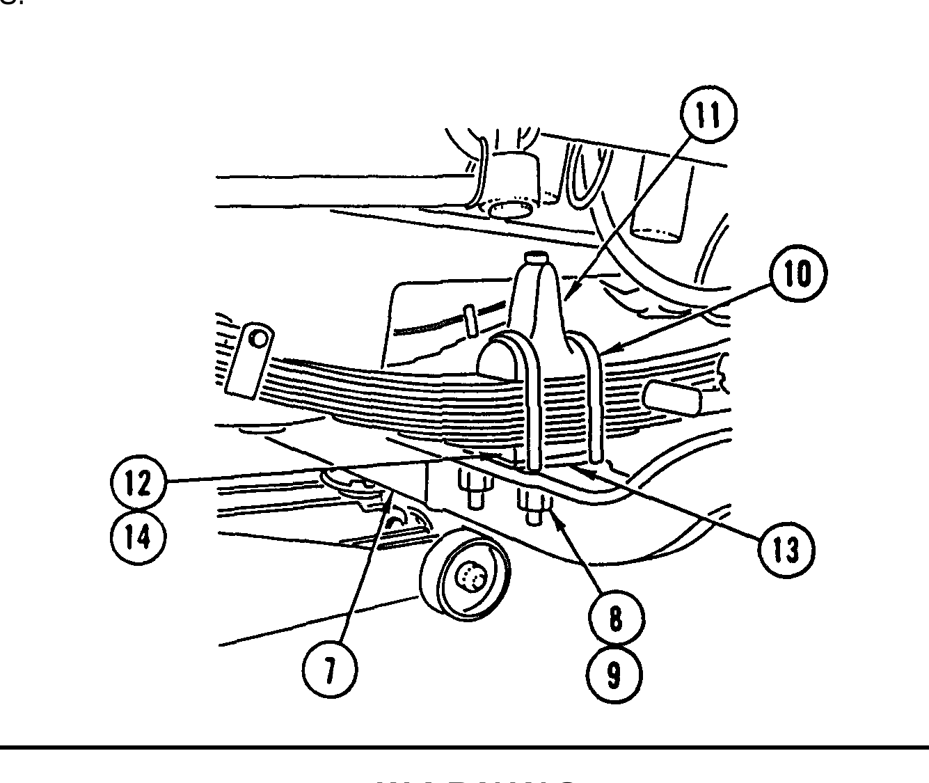
1. ON LEFT SIDE, REMOVE COTTER PIN (1) AND CASTELLATED NUT (2) AND SET DRAG LINK (3) ASIDE. DISCARD COTTER PIN.
2. REMOVE TWO COTTER PINS (4), TWO CASTELLATED NUTS (5), AND TIE ROD (6), DISCARD COTTER PINS.
Front axle weighs 1,060 lb (481 kg). Support front axle with suitable floor jack during removal to prevent possible injury to personnel.
Make sure front of vehicle is blocked up enough to allow removal of axle.
3. POSITION SUITABLE FLOOR JACK UNDER CENTER OF AXLE (7) AND SECURE AXLE TO FLOOR JACK.
4. REMOVE EIGHT NUTS (8), EIGHT WASHERS (9), FOUR U-BOLTS (10), AND TWO AXLE STOPS (11).
5. LOWER AXLE (7) AND REMOVE FROM VEHICLE.
6. REMOVE SPACER (12) AND SHIM (13).
7. REMOVE PIN (14) FROM SPACER (12).
8. USING LIFTING DEVICE, REMOVE AXLE (7) FROM FLOOR JACK.
Use general cleaning methods to clean all parts (page 2-30).
Inspect all parts for wear or damage.
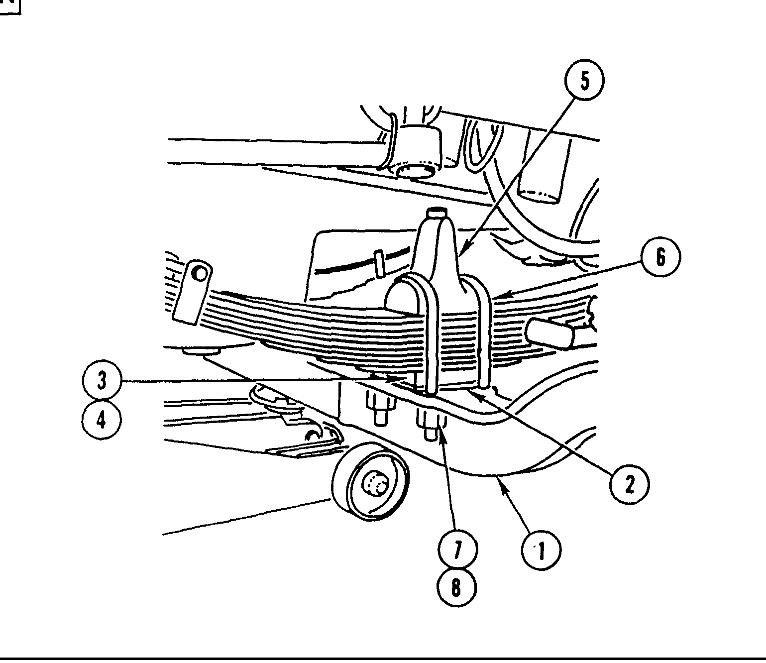
1. WITH AXLE (1) INSTALLED AND SECURED ON SUITABLE FLOOR JACK, POSITION AXLE (1) UNDER VEHICLE.
2. COAT BOTTOM OF SHIM (2) WITH ALUMILASTIC AND INSTALL SHIM (2) ON AXLE (1) WITH WIDE END OF SHIM (2) TOWARD REAR OF VEHICLE.
3. INSTALL PIN (3) IN SPACER (4).
4. COAT TOP OF SPACER (4) WITH ALUMILASTIC AND INSTALL SPACER (4) ON TOP OF SHIM (2).
5. INSTALL AXLE (1).
6. COAT BOTTOM AND U-BOLT SADDLES OF TWO AXLE STOPS (5) With ALUMILASTIC.
7. INSTALL TWO AXLE STOPS (5), FOUR U-BOLTS (6), EIGHT WASHERS (7), AND EIGHT NUTS (8) ON AXLE (1). TIGHTEN NUTS TO 380-460 LB-FT (515-624 N.m).
8. REMOVE FLOOR JACK FROM UNDER VEHICLE.
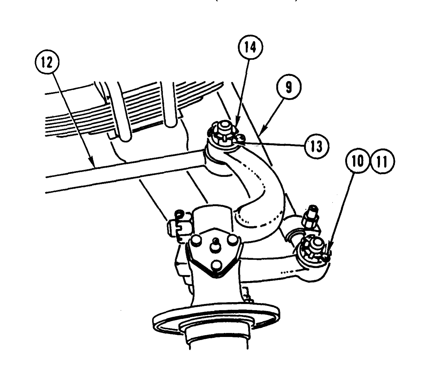
9. INSTALL TIE ROD (9) AND TWO CASTELLATED NUTS (1O). TIGHTEN NUTS TO 165-180 LB-FT (224-244 N.m).
10. INSTALL TWO NEW COTTER PINS (11) THRU TWO CASTELLATED NUTS (1O).
11. ON LEFT SIDE, INSTALL DRAG LINK (12) AND CASTELLATED NUT (13), TIGHTEN NUT TO 165-180 LB-FT (224-244 N.m).
12. INSTALL NEW COTTER PIN (14) THRU CASTELLATED NUT (13).
Install front brake spider and brake chamber bracket (TM 9-2320-363-20). Check and adjust front axle caster alinement (page 5-60).