Equalizing Beam Replacement
TM 9-2320-363-34-1 · Chapter 9 — Suspension Maintenance
This task covers: a. Removal b. Cleaning c. lnspection d. Installation
Applicable Configuration:                           General Safety Instructions:

M915A2
                                                                     WARNING
Tools and Special Equipment:
                                                           Make sure all air lines and
Shop Equipment, SC 4910-95-CL-A31                          fittings are clear of debris.
Tool Kit, SC 5180-90-CL-N05                                Failure to do so could result in
                                                           equipment failure and/or injury
Materials/Parts:                                           to personnel.
Adapter (8)                 P/N 45163

References:
TM 9-2320-363-20

Equipment Condition:

Reference                   Condition Description
TM 9-2320-363-20            Air System Drained
TM 9-2320-363-20            Rear Brakeshoe and
                            Linings Removed
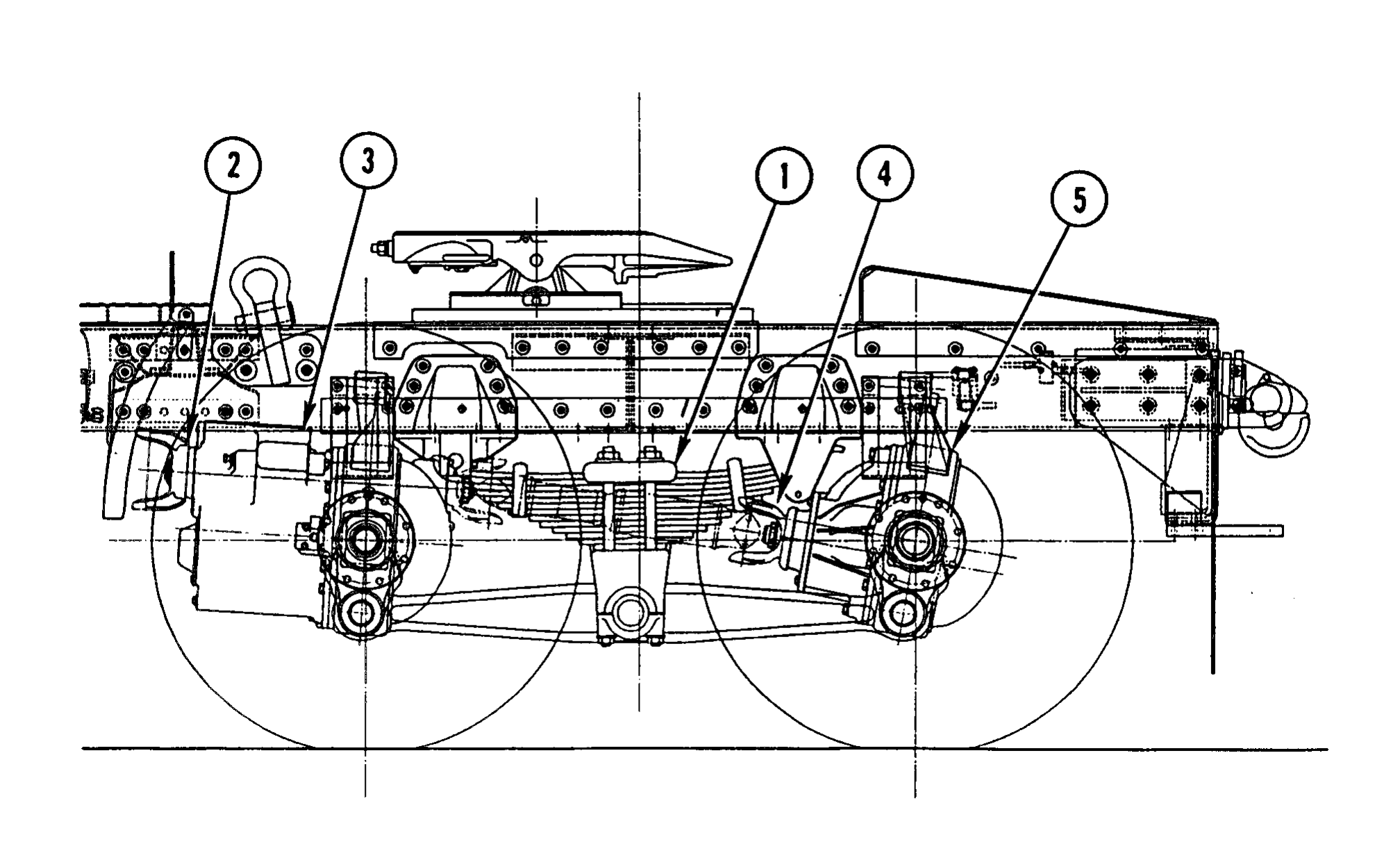
1. USING SUITABLE LIFTING DEVICE AND JACK STANDS, LIFT AND SUPPORT REAR OF VEHICLE SO THAT WEIGHT IS RELIEVED FROM BOTH REAR SPRINGS (1).
2. POSITION JACK STAND TO SUPPORT INPUT YOKE (2) OF FORWARD-REAR AXLE (3). POSITION JACK STAND TO SUPPORT INPUT YOKE (4) OF REAR AXLE (5).
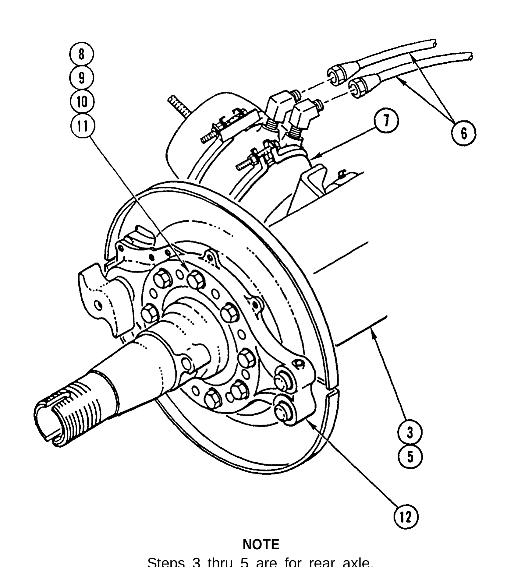
3. REMOVE FOUR AIR HOSES (6) FROM REAR BRAKE CHAMBERS (7).
4. REMOVE 16 NUTS (8), 16 WASHERS (9), 16 SCREWS (10), 16 WASHERS (11), AND 2 SPIDER ASSEMBLIES (12) FROM BOTH SIDES OF REAR AXLE (5).
5. USING SUITABLE FLOOR JACK, SUPPORT REAR AXLE (5).
6. REPEAT STEPS 3 THRU 5 FOR FORWARD-REAR AXLE (3).
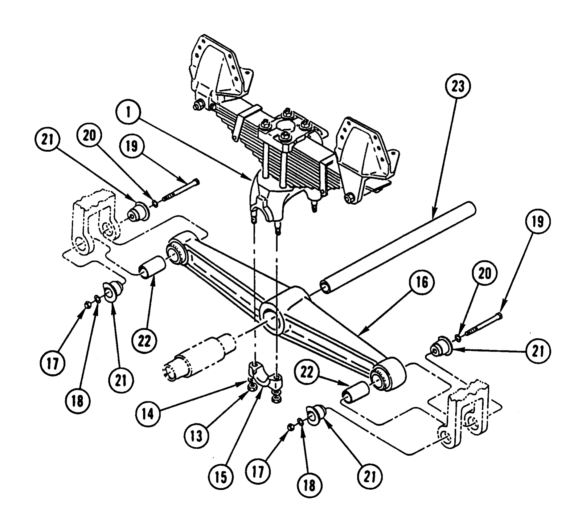
7. REMOVE EIGHT NUTS (13), EIGHT WASHERS (14), AND FOUR SADDLE CAPS (15) FROM TWO SPRING ASSEMBLIES (1).
8. USING BLOCK OF WOOD AND JACK STAND, SUPPORT REAR ENDS OF TWO EQUALIZING BEAMS (16). REMOVE TWO NUTS (17), TWO WASHERS (18), TWO SCREWS (19), TWO WASHERS (20), AND FOUR ADAPTERS (21) FROM REAR END OF TWO EQUALIZING BEAMS (16). DISCARD ADAPTERS.
9. LOWER REAR ENDS OF TWO EQUALIZING BEAMS (16) ONTO BLOCKS.
10. REPEAT STEPS 8 AND 9 FOR FRONT END OF TWO EQUALIZING BEAMS (16).
11. REMOVE FOUR INTERMEDIATE TUBES (22) FROM TWO EQUALIZING BEAMS (16).
12. REMOVE ONE EQUALIZING BEAM (16) FROM BLOCKS AND REMOVE CROSSTUBE (23) FROM OTHER EQUALIZING BEAM (16).
Use general cleaning methods to clean all parts (page 2-30).
Inspect all parts for wear or damage.
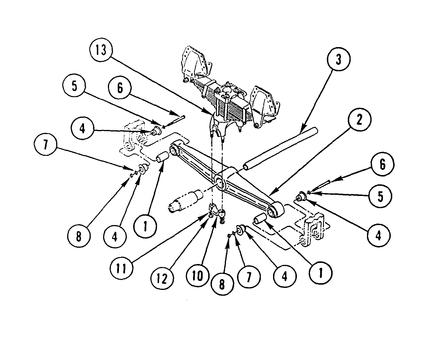
1. INSTALL FOUR INTERMEDIATE TUBES (1) IN TWO EQUALIZING BEAMS (2).
2. POSITION ONE EQUALIZING BEAM (2) . ON BLOCKS UNDER VEHICLE AND INSTALL CROSSTUBE (3).
3. INSTALL SECOND EQUALIZING BEAM (2) ON CROSSTUBE (3) AND BLOCKS UNDER VEHICLE.
Rotate adapters so flat side is vertical. Do not tighten adapters until both ends are installed.
4. USING BLOCK OF WOOD AND JACK STAND, RAISE REAR ENDS OF TWO EQUALIZING BEAMS (2). INSTALL FOUR NEW ADAPTERS (4), TWO WASHERS (5), TWO SCREWS (6), TWO WASHERS (7), AND TWO NUTS (8) HAND-TIGHT.
5. REPEAT STEP 4 FOR FRONT END OF TWO EQUALIZING BEAMS (2) IN FORWARD-REAR AXLE (9).
6. TIGHTEN FOUR NUTS (8) TO 210-240 LB-FT (285-325 N.m).
7. INSTALL FOUR SADDLE CAPS (10), EIGHT WASHERS (11), AND EIGHT NUTS (12) ON TWO SPRING ASSEMBLIES (13). TIGHTEN NUTS TO 225-275 LB-FT (305-373 N.m).
8. REPOSITION FLOOR JACK FROM STEP 5 OF REMOVAL AND INSTALL 2 SPIDER ASSEMBLIES (14), 16 WASHERS (15), 16 SCREWS (16), 16 WASHERS (17), AND 16 NUTS (18) ON BOTH SIDES OF FORWARD-REAR AXLE (9). TIGHTEN NUTS TO 150-175 LB-FT (203.4-237.3 N.m) IN SEQUENCE SHOWN.
9. INSTALL FOUR AIR HOSES (19) IN BRAKE CHAMBERS (20).
10. REPEAT STEPS 8 AND 9 FOR REAR AXLE (21).
Install rear brakeshoe and linings (TM 9-2320-363-20).
EQUALIZING           BEAM      REPLACEMENT

This task covers:        a. Removal b. Cleaning   c. Inspection d. Installation
Applicable Configuration: General Safety Instructions:
All except M915A2
Tools and Special Equipment: Make sure all air lines and fittings are clear of debris. Failure to do so could result in Shop Equipment, SC 4910-95-CL-A31 equipment failure and/or injury to personnel. Tool Kit, SC 5180-90-CL-N05
Materials/Parts:
Adapter (4) P/N 45871
Mounting Hardware PIN 56659-001 Set
References:
TM 9-2320-363-20
Equipment Condition:
Reference Condition Description
TM 9-2320-363-20 Air System Drained
TM 9-2320-363-20 Rear Brakeshoe and Linings Removed
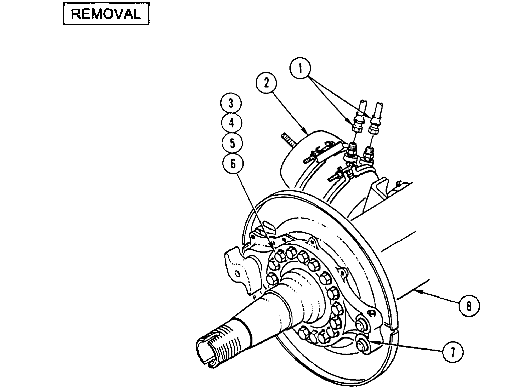
1. USING SUITABLE LIFTING DEVICE AND JACK STANDS, LIFT AND SUPPORT REAR OF VEHICLE SO THAT WEIGHT IS RELIEVED FROM BOTH REAR SPRINGS
2. REMOVE TWO AIR HOSES (1) FROM REAR BRAKE (2).
3. REMOVE 16 NUTS (3), 16 WASHERS (4), 16 SCREWS (5), 16 WASHERS (6), AND SPIDER ASSEMBLY (7) FROM REAR AXLE (8).
4. USING SUITABLE JACK STAND, SUPPORT REAR AXLE (8).
5. REPEAT STEPS 2 THRU 4 FOR FORWARD-REAR AXLE (9).
6. REMOVE FOUR NUTS (10), FOUR WASHERS (11), AND TWO SADDLE CAPS (12) FROM SPRING ASSEMBLY (13).
When saddle caps are removed, spring assembly should raise enough to allow removal of sleeve and crosstube. If spring assembly does not raise far enough, lift vehicle enough to remove sleeve and crosstube.
7. REMOVE SLEEVE (14), CROSS TUBE (15), AND FOUR WASHERS (16) FROM EQUALIZING BEAM (17).
8. USING FLOOR JACK, SUPPORT REAR END OF EQUALIZING BEAM (17). REMOVE NUT (18), WASHER (19), SCREW (20), WASHER (21), AND TWO ADAPTERS (22). DISCARD ADAPTERS.
9. LOWER END OF EQUALIZING BEAM (17) ONTO BLOCKS AND REMOVE INTERMEDIATE TUBE (23).
10. REPEAT STEPS 8 AND 9 FOR FRONT END OF EQUALIZING BEAM (17).
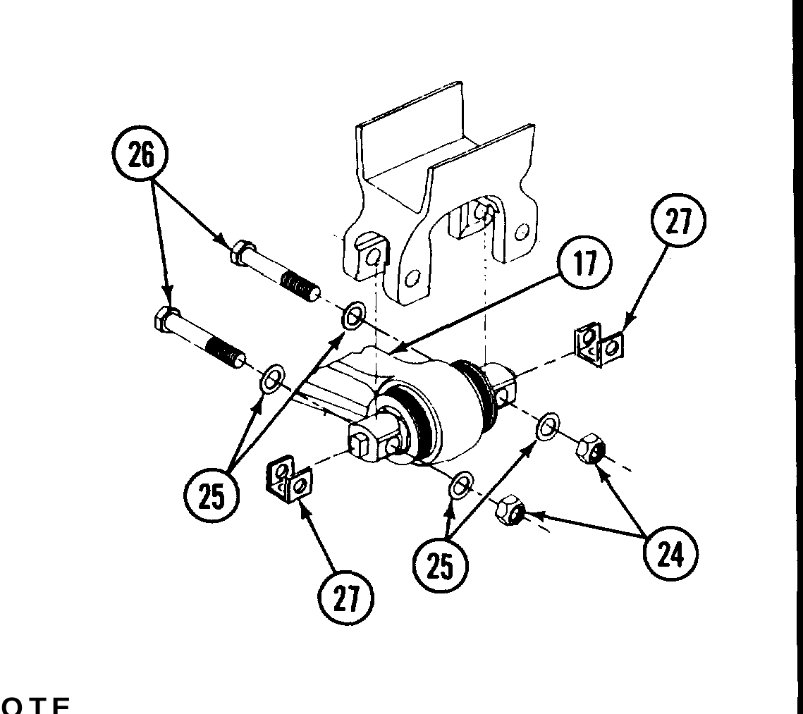
11. USING FLOOR JACK, SUPPORT REAR END OF EQUALIZING BEAM (17). REMOVE TWO NUTS (24), WASHERS (25), AND BOLTS (26). DISCARD ALL MOUNTING HARDWARE.
12. LOWER REAR END OF EQUALIZING BEAM (17) AND REMOVE SHIMS (27). TAG SHIMS FOR INSTALLATION.
13. LOWER FRONT END OF EQUALIZING BEAM (17) AND REMOVE SHIMS (27). TAG SHIMS FOR INSTALLATION.
Use general cleaning methods to clean all parts (page 2-30).
Inspect all parts for wear or damage.
1. INSTALL INTERMEDIATE TUBE (1).
2. USING SUITABLE LIFTING DEVICE, POSITION FRONT END OF EQUALIZING BEAM (2) IN MOUNTING BRACKET OF FORWARD-REAR AXLE (3).
3. INSTALL TWO NEW ADAPTERS (4), WASHER (5), SCREW (6), WASHER (7), AND NUT (8).
4. REPEAT STEPS 1 THRU 3 FOR REAR END OF EQUALIZING BEAM (2) IN REAR AXLE (9).
5. TIGHTEN TWO NUTS (8) ON BOTH ENDS OF EQUALIZING BEAM (2) TO 210-240 LB-FT (285-325 N.m).
9-32 Change 1
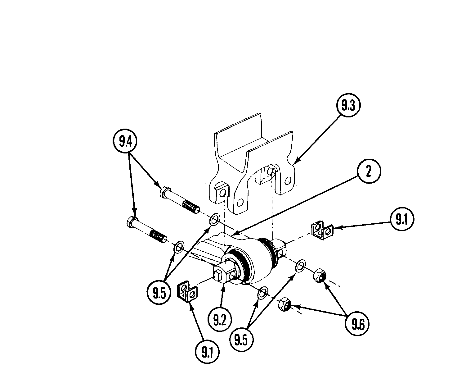
l Perform steps 5.1 through 5.6 for M916A2, M917A1, and M917A1 w/MCS only.
l Same number of shims as removed must be installed, in the same location as removed from.
5.1. POSITION SHIMS (9.1) ON BAR PINS (9.2).
5.2. USING FLOOR JACK, SUPPORT AND RAISE FRONT OF EQUALIZING BEAM (2) INTO AXLE MOUNTING BRACKET (9.3).
5.3. INSTALL TWO NEW BOLTS (9.4), WASHERS (9.5), AND NUTS (9.6).
5.4. USING FLOOR JACK, SUPPORT AND RAISE REAR OF EQUALIZING BEAM (2) INTO AXLE MOUNTING BRACKET (9.3).
5.5. INSTALL TWO NEW BOLTS (9.4), WASHERS (9.5), AND NUTS (9.6).
5.6. TIGHTEN TWO FRONT AND TWO REAR NUTS (9.6) TO 450-600 LB-FT (610-814 N.m).
6. INSTALL FOUR WASHERS (10), CROSSTUBE (11), AND SLEEVE (12).
7. INSTALL TWO SADDLE CAPS (13), FOUR WASHERS (14), AND FOUR NUTS (15) ON SPRING ASSEMBLY (16). TIGHTEN NUTS TO 225-275 LB-FT (305-373 N.m).
8. REPOSITION JACK STAND FROM STEP 4 OF REMOVAL AND INSTALL SPIDER ASSEMBLY (17), 16 WASHERS (18), 16 SCREWS (19), 16 WASHERS (20), AND 16 NUTS (21) ON FORWARD- REAR AXLE (3). TIGHTEN NUTS TO 150-175 LB-FT (203.4-237.3 N.m) IN SEQUENCE SHOWN.
9. INSTALL TWO AIR HOSES (22) IN FORWARD-REAR BRAKE CHAMBER (23).
10. REPEAT STEPS 8 AND 9 FOR REAR AXLE.
Install rear brakeshoe and linings (TM 9-2320-363-20).
This chapter illustrates and describes procedures for maintenance of the body, cab, hood, and hull and related parts. A list of tasks contained in this chapter is shown below.
Page
Seat Cover and Pad Repair . . . . . . . . . . . . . . . . . . . . . . . . . . . . . . . . . . . . . . . . . 10-2
Dashboard Replacement . . . . . . . . . . . . . . . . . . . . . . . . . . . . . . . . . . . . . . . . . . . 10-3
Air Ducts Replacement (M915A2 and M916A1) . . . . . . . . . . . . . . . . . . . . . . . . . . 10-36
Air Ducts Replacement (All Except M915A2 and M916A1) . . . . . . . . . . . . . . . . . . 10-39.0
Front Cab Mounts Replacement . . . . . . . . . . . . . . . . . . . . . . . . . . . . . . . . . . . . . . 10-40
Rear Cab Mounts Replacement . . . . . . . . . . . . . . . . . . . . . . . . . . . . . . . . . . . . . . 10-49
Windshield Replacement . . . . . . . . . . . . . . . . . . . . . . . . . . . . . . . . . . . . . . . . . . . 10-52
Cab Replacement (M915A2) ........................................ 10-64
Cab Replacement (All Except M915A2) . . . . . . . . . . . . . . . . . . . . . . . . . . . . . . . . 10-75
Rear Window Replacement . . . . . . . . . . . . . . . . . . . . . . . . . . . . . . . . . . . . . . . . . 10-84
Cab Door Replacement . . . . . . . . . . . . . . . . . . . . . . . . . . . . . . . . . . . . . . . . . . . . 10-89