Rear-Rear Axle Differential Carrier Replacement
TM 9-2320-363-34-1 · Chapter 6 — Rear Axle Maintenance
This task covers: a. Removal b. Cleaning c. Inspection d. Installation
Tools and Special Equipment:                        General Safety Instructions:
Shop Equipment, SC 4910-95-CL-A31
Tool Kit, SC 5180-90-CL-N05                                            WARNING
                                                           l     Rear-rear axle differential
Materials/Parts:
                                                               carrier weighs 860 lb (390
Washer, Lock (12)         P/N 1229U1503                        kg). Attach suitable floor jack
                                                               prior to removal or installation
Compound, Sealing         Appendix B, Item 16
                                                               to prevent possible injury to
Personnel Required: (2)                                        personnel.

References:                                                l     Adhesives, s o l v e n t s , a n d
                                                               sealing compounds can burn
                                                               easily, can give off harmful
TM 9-2320-363-20                                               vapors, and are harmful to
                                                               skin and clothing. To avoid
Equipment Condition:                                           injury or death, keep away
                                                               from open fire and use in
Reference                 Condition Description                well-ventilated       area. If
TM 9-2320-363-20          Axle Shafts Removed                  adhesive, solvent, or sealing
                                                               compound gets on skin or
TM 9-2320-363-20          Intermediate Driveline               clothing, wash immediately
                          Disconnected                         with soap and water.
TM 9-2320-363-20          Axle Oil Drained
                                                           l     Spilled gear oil is very
                                                               slippery. Wipe up any spilled
                                                               oil immediately. Failure to do
                                                               so could result in serious
                                                               injury to personnel.
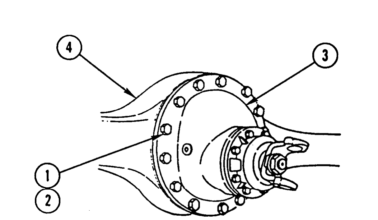
If axle assembly has been removed from vehicle, perform steps 1 thru 3 only.
1. REMOVE 12 CAPSCREWS (1) AND 12 LOCK WASHERS (2). DISCARD LOCK WASHERS.
2. LOOSEN DIFFERENTIAL CARRIER (3) BY TAPPING AROUND FLANGE.
3. REMOVE DIFFERENTIAL CARRIER (3) FROM AXLE (4). DISCARD LOCK WASHERS.
4. LOWER DIFFERENTIAL CARRIER (3) ONTO FLOOR JACK AND ROLL DIFFERENTIAL CARRIER (3) FROM UNDER VEHICLE.
Use general cleaning methods to clean all parts (page 2-30).
Inspect all parts for wear or damage.
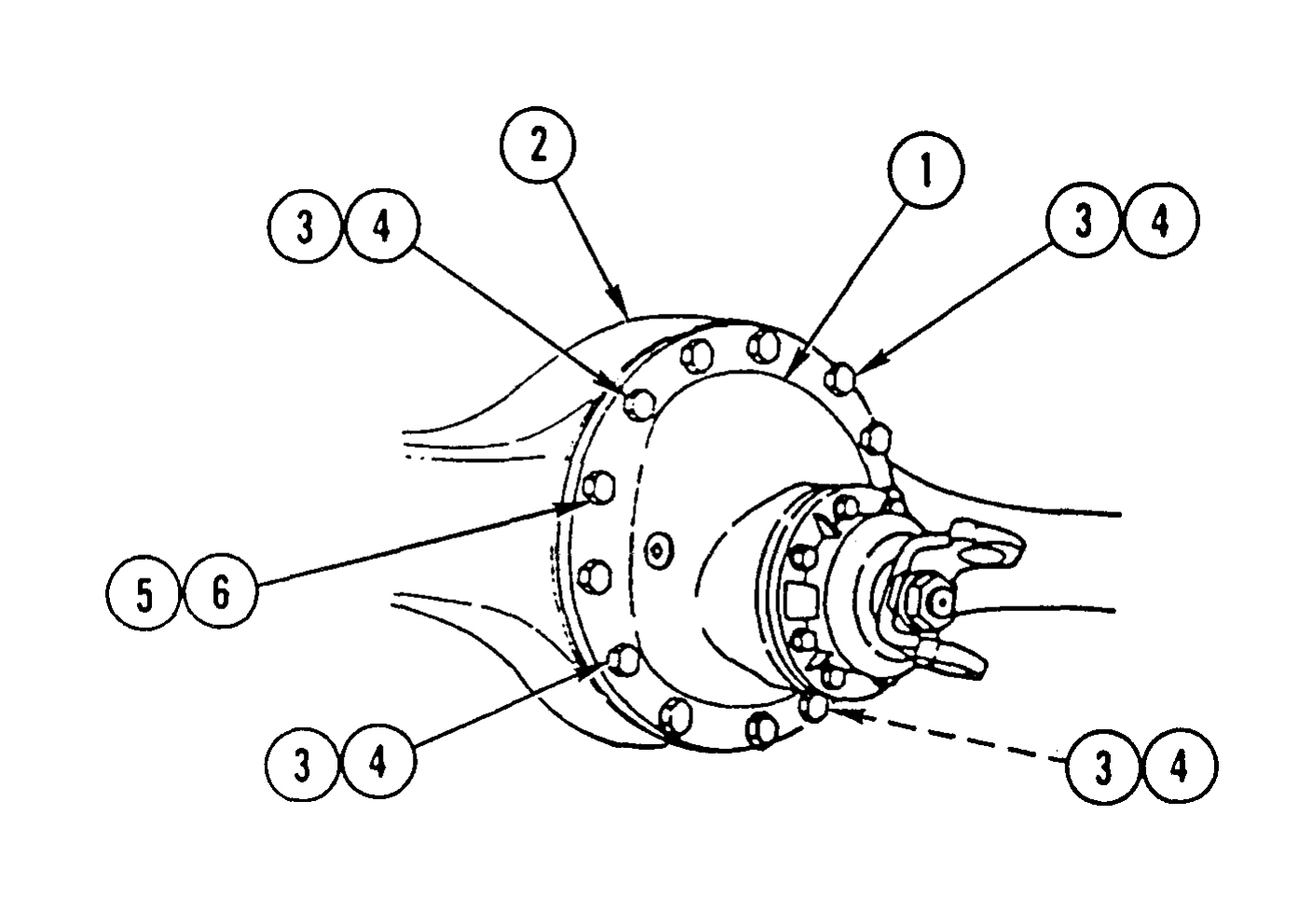
1. INSTALL DIFFERENTIAL CARRIER (1) ON FLOOR JACK AND ROLL DIFFERENTIAL CARRIER (1) INTO POSITION UNDER VEHICLE.
2. APPLY 1/8-lN. BEAD OF SEALING COMPOUND AROUND ENTIRE MATING SURFACE OF AXLE (2).

3. ATTACH SUITABLE HOIST AND INSTALL DIFFERENTIAL CARRIER (1), FOUR NEW LOCK WASHERS (3), AND FOUR CAPSCREWS (4) IN FOUR CORNER LOCATIONS AROUND DIFFERENTIAL CARRIER (1). HAND-TIGHTEN CAPSCREWS.
4. SEAT DIFFERENTIAL CARRIER (1) AND TIGHTEN FOUR CAPSCREWS (4) IN PATTERN OPPOSITE EACH OTHER.
5. REPEAT STEP 4 UNTIL DIFFERENTIAL CARRIER (1) IS COMPLETELY SEATED. TIGHTEN FOUR CAPSCREWS (4) TO 150-230 LB-FT (203-312 N.m).
6. INSTALL EIGHT NEW LOCK WASHERS (5) AND EIGHT CAPSCREWS (6). TIGHTEN EIGHT CAPSCREWS (6) TO 150-230 LB-FT (203-312 N.m).
Connect intermediate driveline (TM 9-2320-363-20). Install axle shafts (TM 9-2320-363-20). Fill axle with oil (TM 9-2320-363-20).