Front Engine Mount Adapter Replacement
TM 9-2320-363-34-1 · Chapter 3 — Power Package Maintenance
This task covers: a. Removal b. Cleaning c. Inspection d. Installation
Tools and Special Equipment:                            General Safety Instructions:

Shop Equipment, SC 4910-95-CL-A31
Tool Kit, SC 5180-90-CL-N05                                             WARNING
                                                               Engine weighs 2,850 lb (1294
Materials/Parts:
                                                               kg). Support engine from lower
Nut, Lock (2)                                                  block pan rail. Failure to do so
                                                               could result in injury to
Personnel Required: (2)                                        personnel and damage to
                                                               equipment.
Equipment Condition:

Reference                 Condition Description
Page 3-122                Vibration Damper
                          Removed

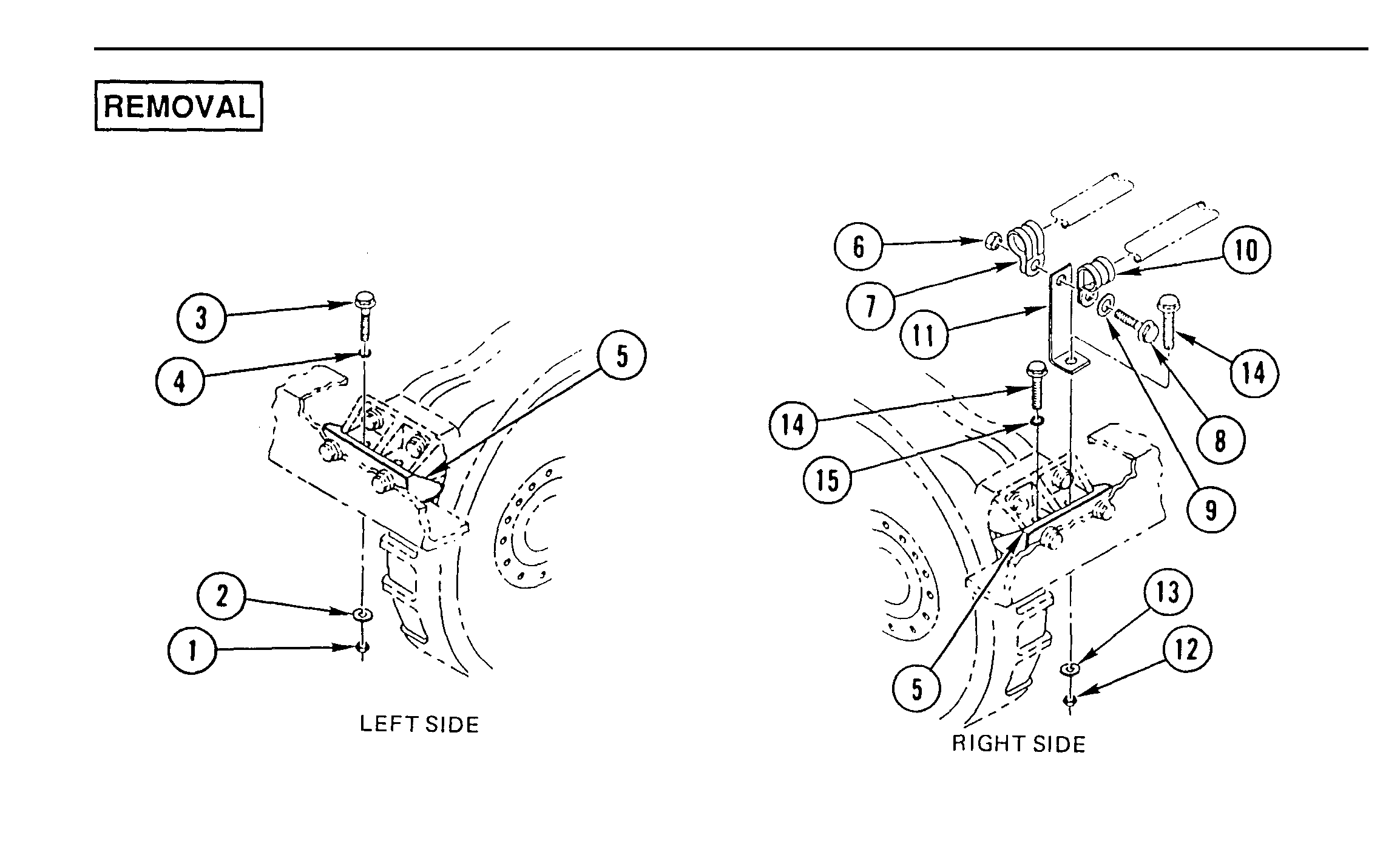
1.   REMOVE TWO LOCK NUTS (1), TWO WASHERS (2) TWO SCREWS (3), TWO WASHERS (4),
     TWO ISOLATORS (5), AND TWO SLEEVES (6) FROM FRONT ENGINE MOUNT ADAPTER (7).
     DISCARD LOCK NUTS.

                                          WARNING
         Engine weighs 2,850 lb (1294 kg). Support engine from lower block pan rail.
         Failure to do so could result in injury to personnel and damage to equipment.

2.     SUPPORT ENGINE (8) AND REMOVE SPACER (9) AND TWO ISOLATORS (10).

3.     REMOVE FOUR BOLTS (11) AND FRONT ENGINE MOUNT ADAPTER (7).

       Use general cleaning methods to clean all parts (page 2-30).

       Inspect all parts for wear or damage.
TM page 3-47
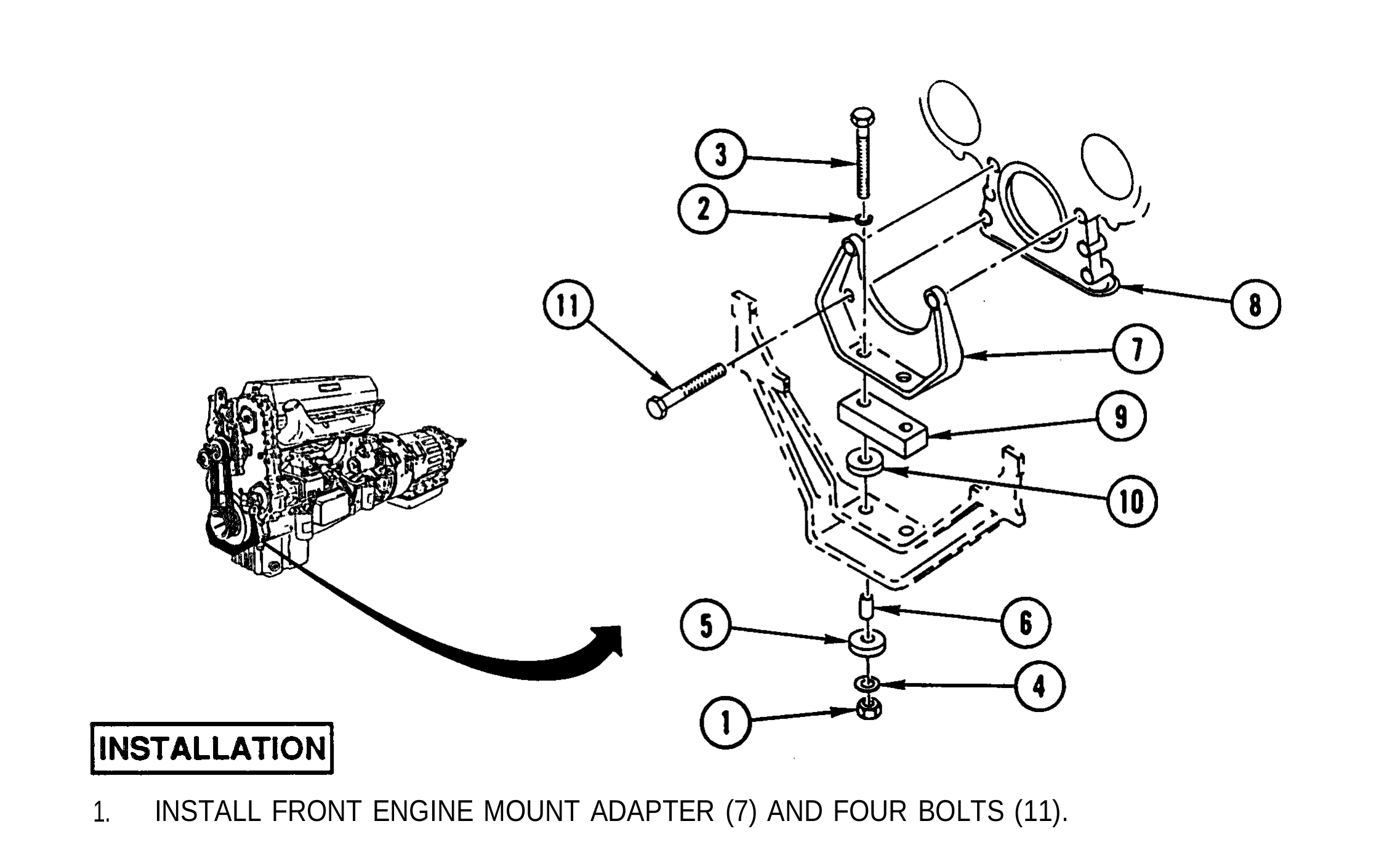
1. INSTALL FRONT ENGINE MOUNT ADAPTER (7) AND FOUR BOLTS (11).
2. INSTALL TWO ISOLATORS (10) AND SPACER (9).
3. LOWER ENGINE (8) AND REMOVE ENGINE SUPPORT.
4. INSTALL TWO SLEEVES (6), TWO ISOLATORS (5), TWO WASHERS (4), TWO SCREWS (3), TWO WASHERS (2), AND TWO NEW LOCK NUTS (1).
NOTE Follow-on Maintenance:
Install vibration damper (page 3-122).
TM page 3-48