Crankshaft Front Oil Seal Replacement
TM 9-2320-363-34-1 · Chapter 3 — Power Package Maintenance
This task covers: a. Removal b. Inspection c. Installation
Tools and Special Equipment:                   Equipment Condition:
Shop Equipment, SC 4910-95-CL-A31              Reference              Condition Description
TOOl Kit, SC 5180-90-CL-N05
Oil Seal Remover, J35993                       Page 3-122             Vibration Damper
(XI Seal Installer, J35686                                            Removed
Oil Seal Expander, J35685-A
Materials/Parts:
Seal, Crankshaft       P/N Y327958TA
Front Oil
Cloth, Abrasive        Appendix B, Item 10
Oil, Lubricating       Appendix B, Item 37
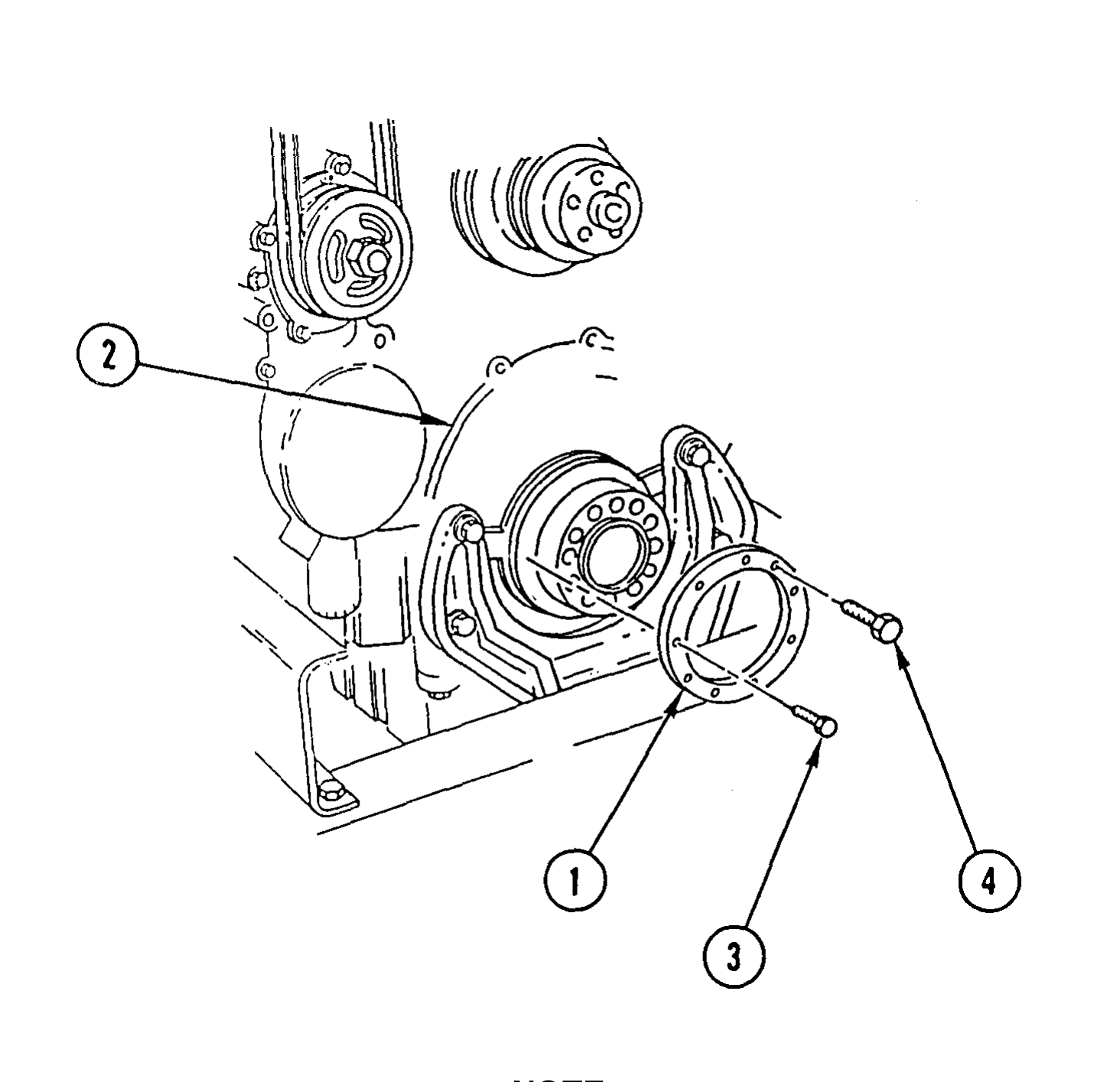
1. INSTALL OIL SEAL REMOVER (1) OVER END OF CRANKSHAFT AND AGAINST GEAR CASE COVER (2). INSTALL SIX SELF-TAPPING SCREWS (3).
2. INSTALL THREE BOLTS (4) IN OIL SEAL REMOVER (1) UNTIL BOLTS (4) CONTACT GEAR CASE COVER (2).
3. WORK CLOCKWISE AND TURN THREE BOLTS (4), ONE AT A TIME, ONE FULL TURN UNTIL OIL SEAL IS REMOVED.
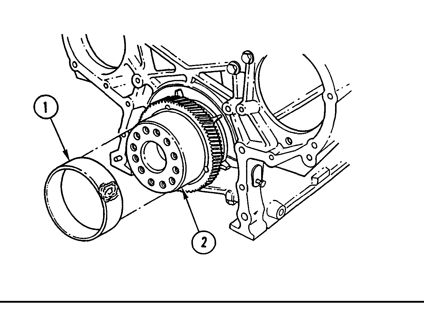
Minor wear line on crankshaft surface should be evident where contact was made with oil seal. This is normal.
1. INSPECT OIL SEAL CONTACT SURFACE OF CRANKSHAFT CAREFULLY.
2. lNSPECT EXPOSED AREA OF CRANKSHAFT FOR DIRT, BURRS, OR ROUGH SURFACES.
3. IF NECESSARY, CLEAN CRANKSHAFT SURFACE WITH ABRASIVE CLOTH.
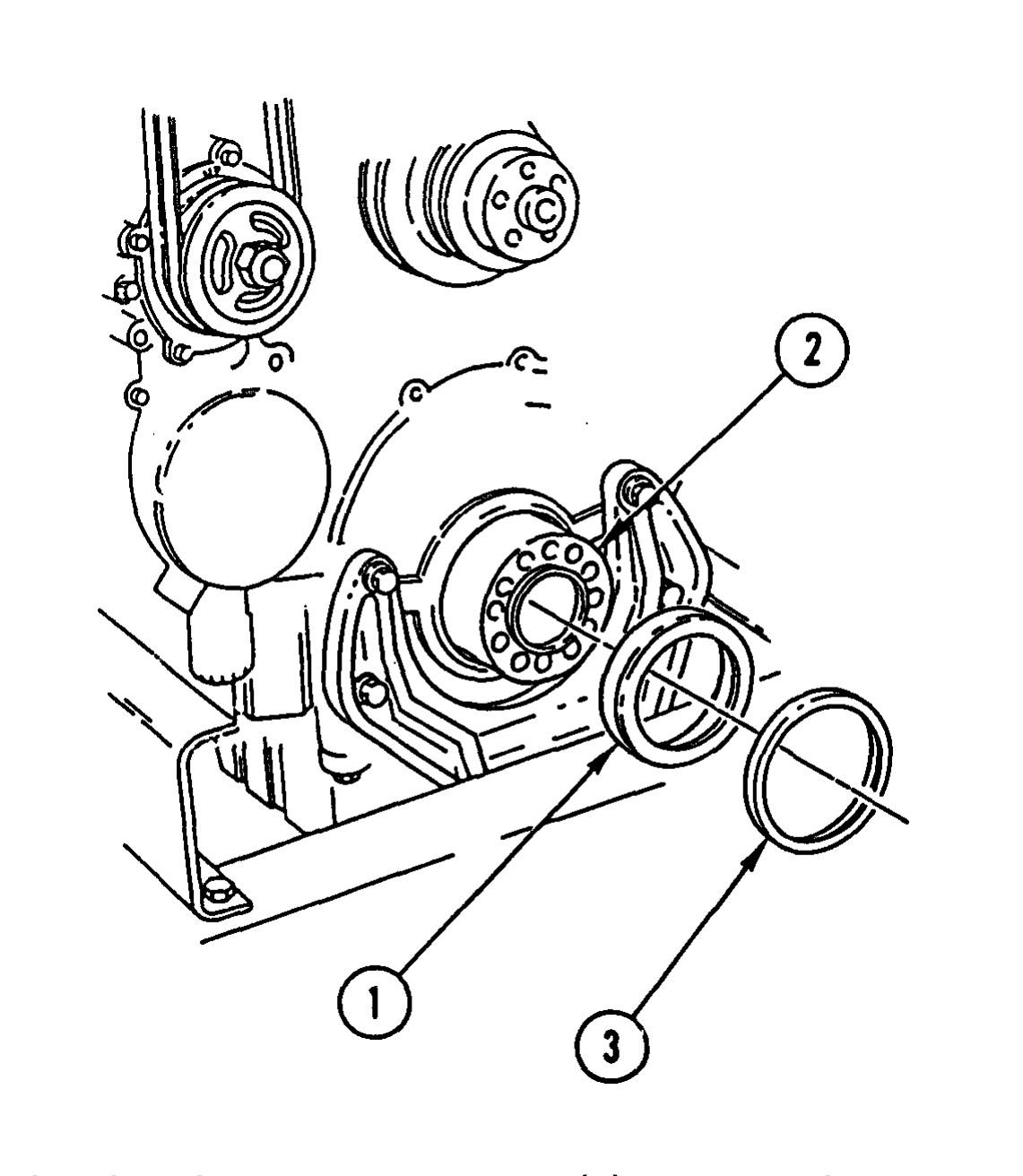
1. COAT OUTSIDE OF OIL SEAL EXPANDER (1) WITH LIGHT FILM OF CLEAN ENGINE LUBRICATING OIL AND INSTALL EXPANDER (1) ON END OF CRANKSHAFT (2).
Before installing oil seal, direction of arrow on oil seal should match engine rotation.
2. INSTALL OIL SEAL (3) OVER OIL SEAL EXPANDER (1) AND ONTO CRANKSHAFT (2) CAREFULLY, AS FAR AS IT WILL GO MANUALLY.
3. REMOVE OIL SEAL EXPANDER (1).
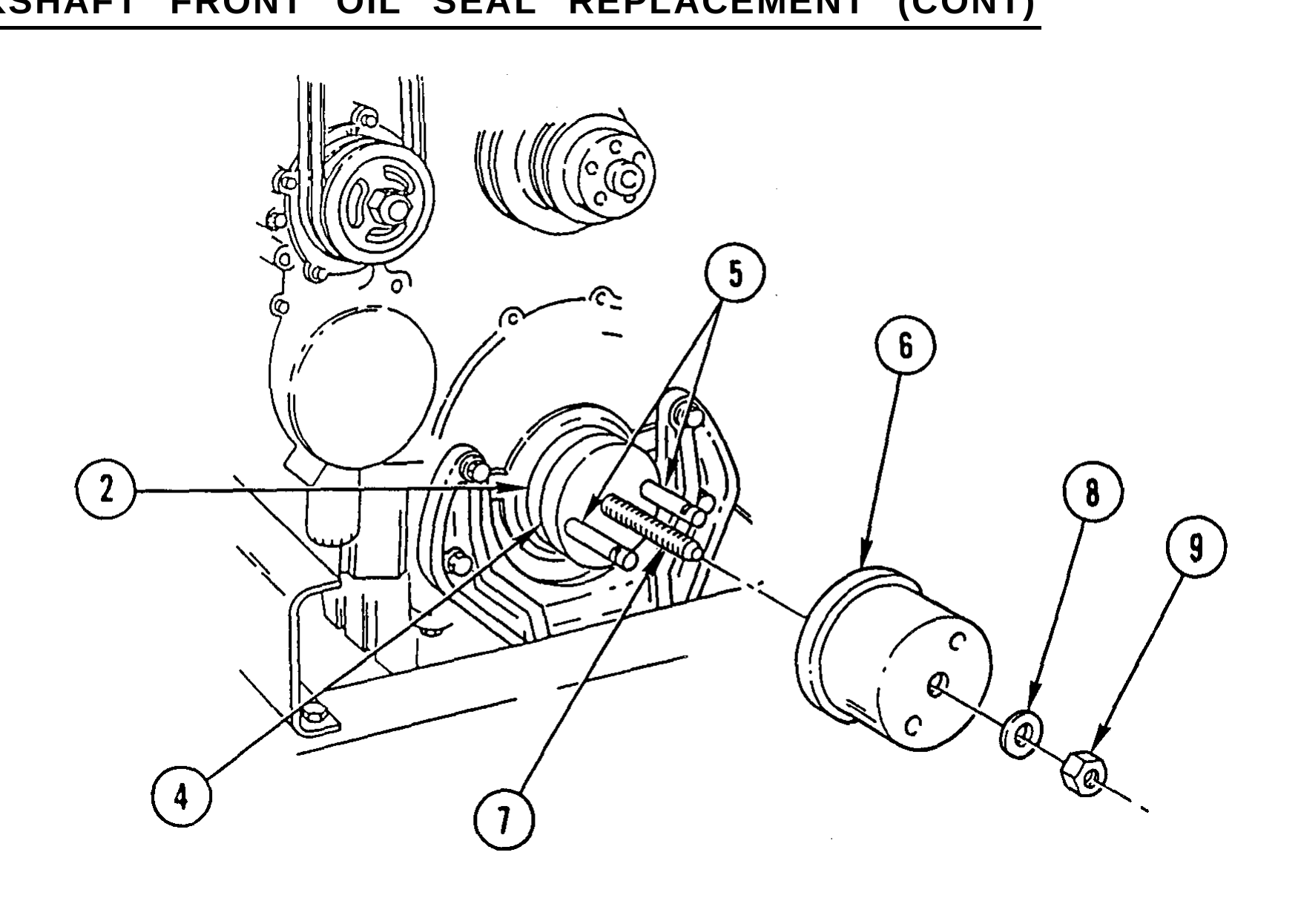
Make sure butt end of crankshaft, both sides of base, and inside of installer housing are clean, smooth, and free of foreign material or damage.
4. POSITION OIL SEAL INSTALLER BASE (4) ON FRONT OF CRANKSHAFT (2).
5. INSTALL TWO GUIDE STUDS (5) THRU TWO HOLES IN INSTALLER BASE (4) AND INTO TWO CRANKSHAFT PULLEY/VIBRATION DAMPER MOUNTING BOLT HOLES 180 DEGREES APART.
6. HAND-TIGHTEN TWO GUIDE STUDS (5) UNTIL INSTALLER BASE (4) IS TIGHT AGAINST END OF CRANKSHAFT (2).
7. INSTALL OIL SEAL INSTALLER HOUSING (6) OVER CENTER SCREW (7) OF INSTALLER BASE (4) AND TWO GUIDE STUDS (5) AND AGAINST OIL SEAL.
8. INSTALL THRUST BEARING (8) ON CENTER SCREW (7) WITH CASE SIDE OF THRUST BEARING AGAINST OIL SEAL INSTALLER HOUSING (6).
9. INSTALL AND TIGHTEN OIL SEAL INSTALLER NUT (9) UNTIL INSIDE SURFACE OF OIL SEAL INSTALLER HOUSING (6) IS FIRMLY SEATED AGAINST INSTALLER BASE (4).
10. REMOVE OIL SEAL INSTALLER NUT (9), THRUST BEARING (8), OIL SEAL INSTALLER HOUSING (6), TWO GUIDE STUDS (5), AND OIL SEAL INSTALLER BASE (4).