2-35.3. (6.2L or 6.5L) FUEL INJECTION PUMPS (DB2829-4523, DB2829-4879, or
TM 9-2815-237-34 · Chapter 2 — Engine Maintenance
DB2831-5149) CALIBRATION USING FUEL INJECTION PUMP TEST STA N D (FTIS) MODEL A8022 This task covers:
a. Mounting Fuel Injection Pump c. Removal of Fuel Injection Pump on Test Stand from Test Stand
b. Test Stand Setup Procedures
INITIAL SETUP:
  Tools                                                Test Equipment
   General mechanic’s tool kit:                         Test stand, model A8022
     automotive (Appendix E, Item 1)
                                                       Materials/Parts
  Special Tools
                                                           Three 5/16-18x1 hex-head capscrews
    Adapter Kit 74-8033 consisting of:
                                                            (Appendix D, Item 55)
     Adapter plate (Appendix E, Item 57)
                                                           Three 3/8-16x1 hex-head capscrews
     Advance indicator (Appendix E, Item 58)
                                                            (Appendix D, Item 56)
     Alignment gauge (Appendix E, Item 59)
                                                           Calibration fluid (Appendix B, Item 4)
     Barring tool (Appendix E, Item 60)
     Connector (Appendix E, Item 61)                   Manual References
     High-pressure lines (Appendix E, Item 62)
                                                        TM 9-2815-237-34P
     Hose assembly (Appendix E, Item 63)
                                                        Instruction manual 74-9225
     Hose assembly (Appendix E, Item 64)
     Male pipe fitting (Appendix E, Item 65)
     Quick-connect plug (Appendix E, Item 66)
     Test adapter (Appendix E, Item 67)
     Test lead, black (Appendix E, Item 68)
     Test lead, red (Appendix E, Item 69)
     Throttle arm positioner assembly
      (Appendix E, Item 70)
     Tubing (Appendix E, Item 71)

                                                 NOT E
                   The following calibration procedures apply to fuel injection pumps
                   DB 2829-4523, DB 2829-4879, or DB 2831-5149 only.

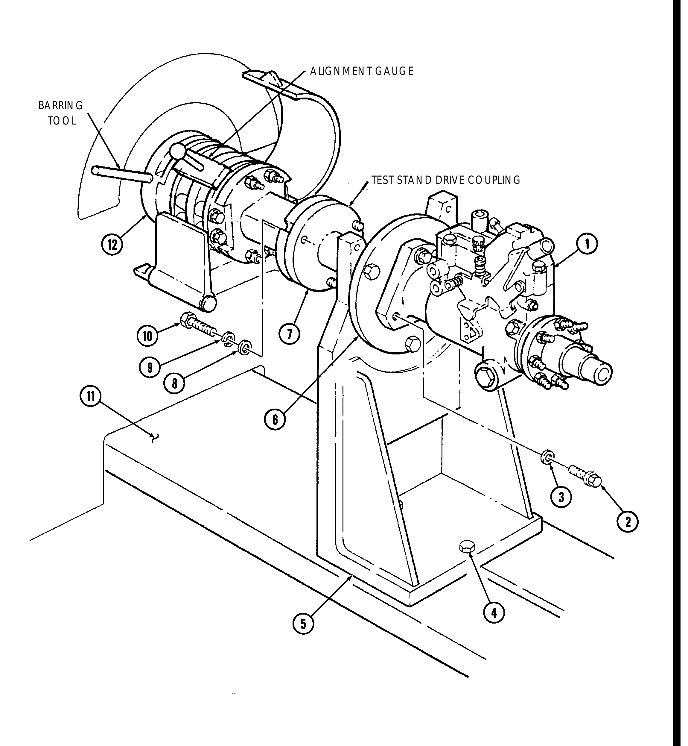
a. Mounting Fuel Injection Pump on Test Stand

                                                  NOT E
                     Prior to installing fuel injection pump to drive coupling, ensure
                     alignment gauge is installed.
 1.   Insert alignment gauge into test stand drive coupling.
 2.   Install fuel injection pump (1) on adapter plate (6) and secure with three 5/16-in. washers (3) and
      5/16-18x1 hex-head capscrews (2).
 3.   Position fuel injection pump (1), with flange mounting bracket (5) installed, to test stand drive
      coupling.
 4.   Using barring tool, rotate driveshaft (12) until tapped holes on pump-mounted drive hub (7) are
      aligned with slots in test stand drive coupling.
 5.   Install three 3/8-in. washers (8), 3/8-in. lockwashers (9), and 3/8-16x1 hex-head capscrews (10) in
      slots and mounting holes on test stand drive coupling and pump-mounted drive hub (7). Remove
      barring tool.
 6.   Tighten two 3/8-16x1 hex-head capscrews (4) that secure flange mounting bracket (5) to
      bedplate (11). Remove alignment gauge.
DB2831-5149) CALIBRATION USING FUEL INJECTION PUMP TEST STA N D (FTIS) MODEL A8022 (Cont’d)
ALIGNMENT GAUGE
BARRING TOOL
TEST STAND DRIVE COUPLING
DB2831-5149) CALIBRATION USING FUEL INJECTION PUMP TEST STA N D (FTIS) MODEL A8022 (Cont’d)
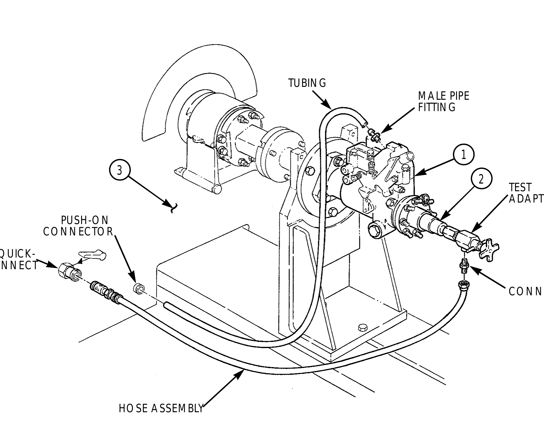
7. Install test adapter and connector on fuel inlet port (2) of fuel injection pump (1).
8. Connect one end of hose assembly to connector and insert other hose end into calibration fluid supply quick-connect on front panel of test stand (3).
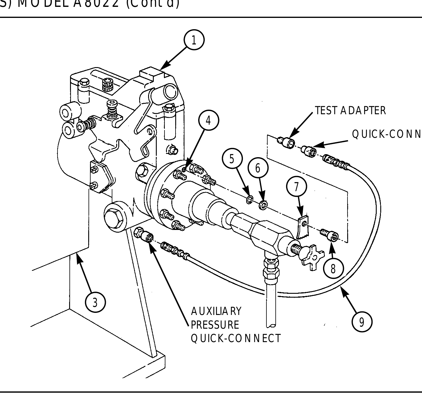
9. Remove screw (8), tab (7), washer (6), and O-ring (5) from fuel injection pump transfer port (4).
10. Position test adapter on fuel injection pump transfer test port (4) and secure into position with existing O-ring (5), tab (7), and washer (6) removed in step 9.
11. Install quick-connect plug into test adapter.
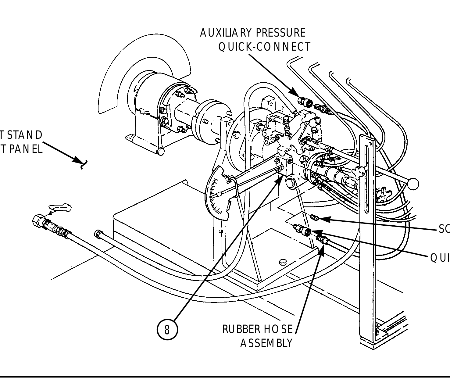
12. Connect one end of rubber hose assembly (9) to quick-connect plug and other hose assembly end to auxiliary pressure quick-connect on front panel of test stand (3).
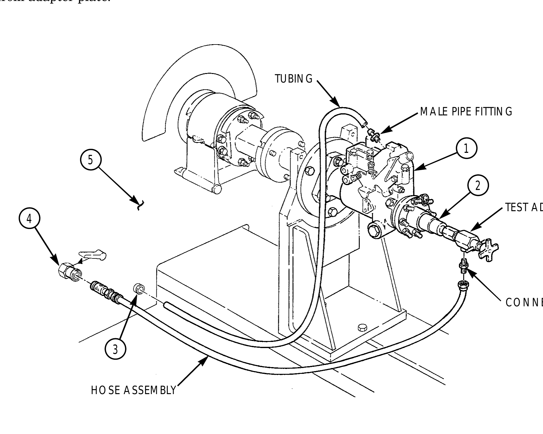
13. Install male pipe fitting on fuel injection pump (1).
14. Connect one end of tubing to male pipe fitting on fuel injection pump (1) and other end to calibration fluid push-on connector on front panel of test stand (3).
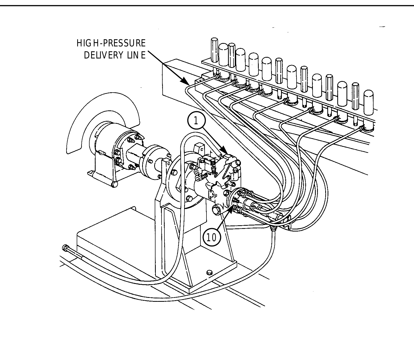
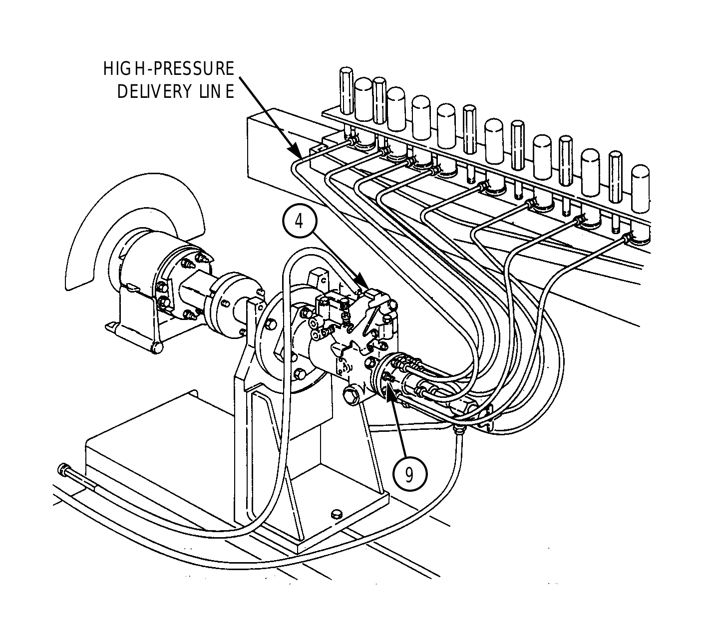
15. Install eight high-pressure delivery lines on discharge fittings (10) of fuel injection pump (1).
TUBING MALE PIPE FITTING
TEST ADAPTER PUSH-ON CONNECTOR QUICK- CONNECT
CONNECTOR
HOSE ASSEMBLY
DB2831-5149) CALIBRATION USING FUEL INJECTION PUMP TEST STA N D (FTIS) MODEL A8022 (Cont’d)
TEST ADAPTER QUICK-CONNECT PLUG
AUXILIARY PRESSURE 9 QUICK-CONNECT
HIGH-PRESSURE DELIVERY LINE
DB2831-5149) CALIBRATION USING FUEL INJECTION PUMP TEST STA N D (FTIS) MODEL A8022 (Cont’d)
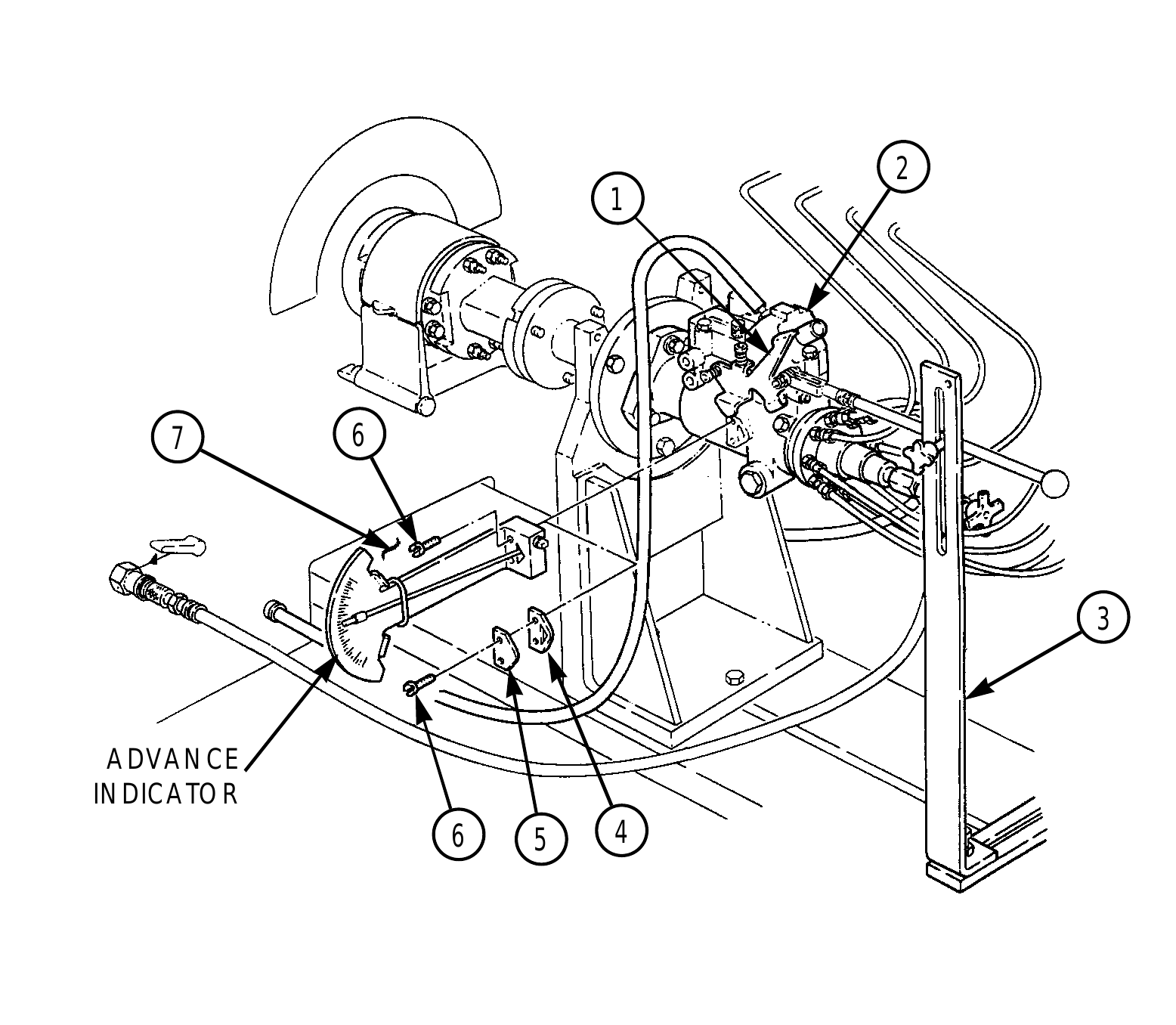
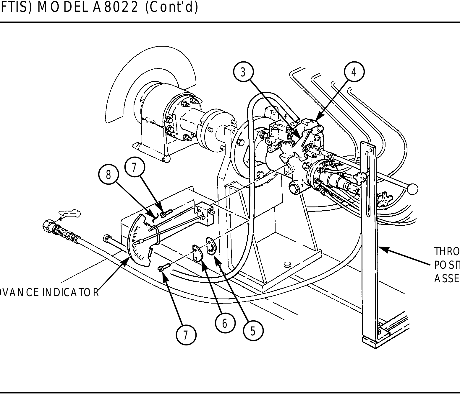
16. Position throttle arm positioner assembly (3) on bedplate (7) and throttle lever (1).
17. Remove two screws (6), timing cover (5), and gasket (4) from fuel injection pump (2) and install advance indicator with two screws (6).
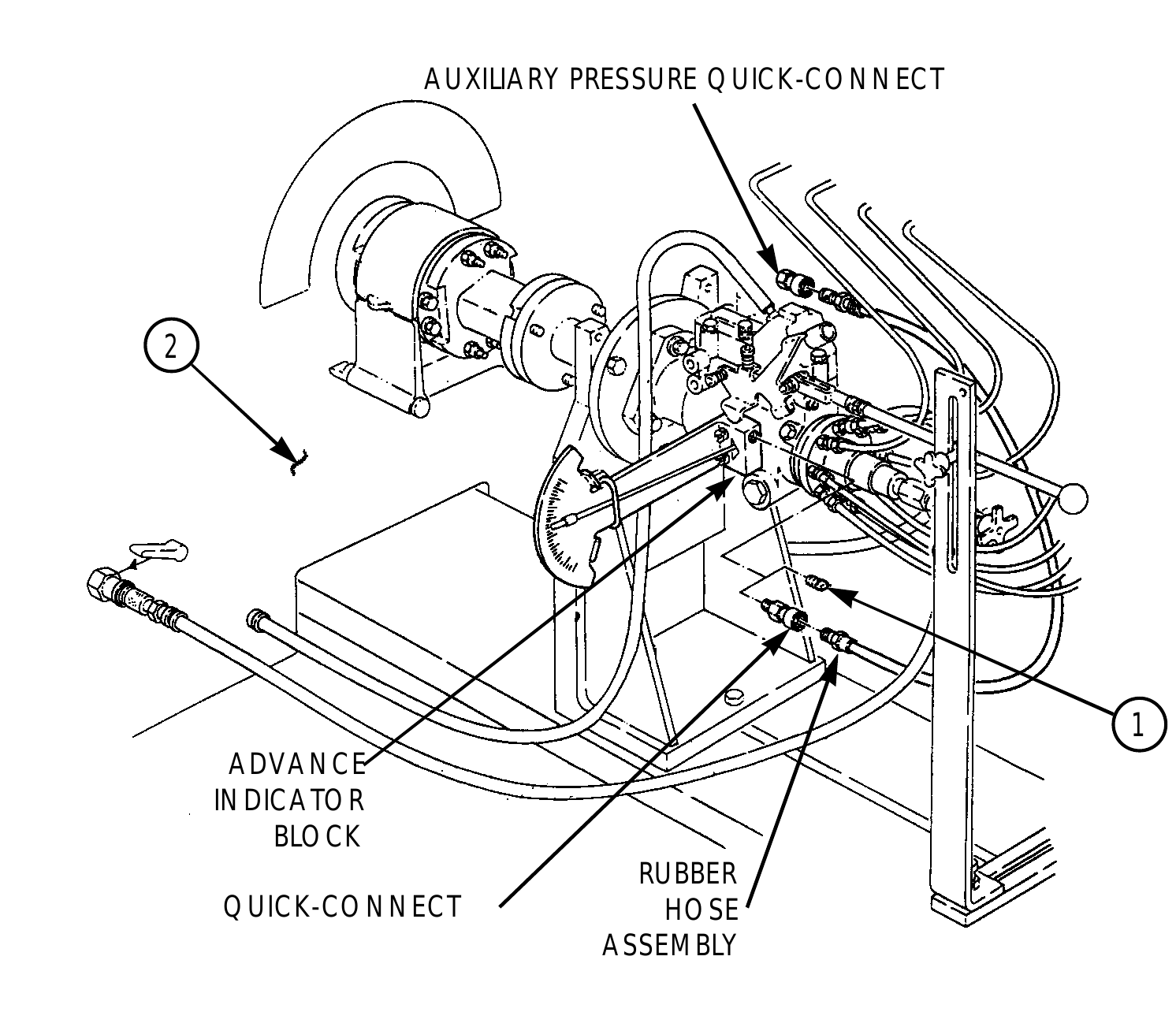
18. Remove screw plug from advance indicator block and install quick-connect on advance indicator block (8).
19. Attach one end of rubber hose assembly to quick-connect and the other hose assembly end to auxiliary pressure quick-connect plug on front panel of test stand.
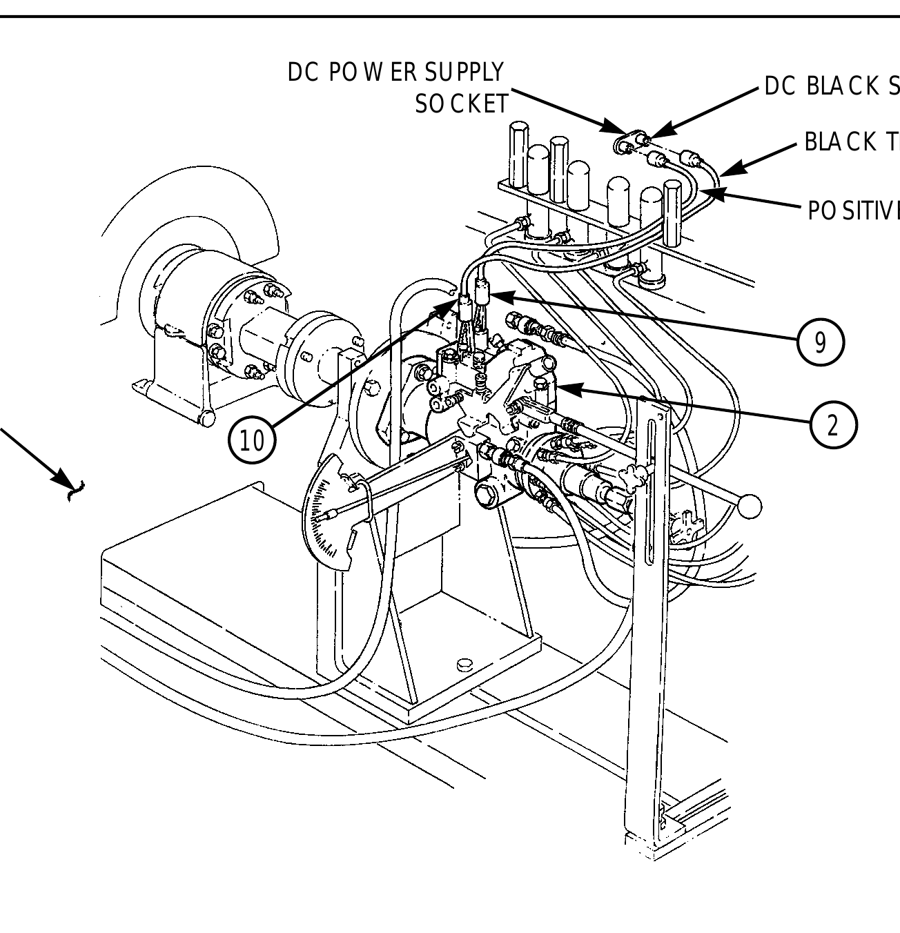
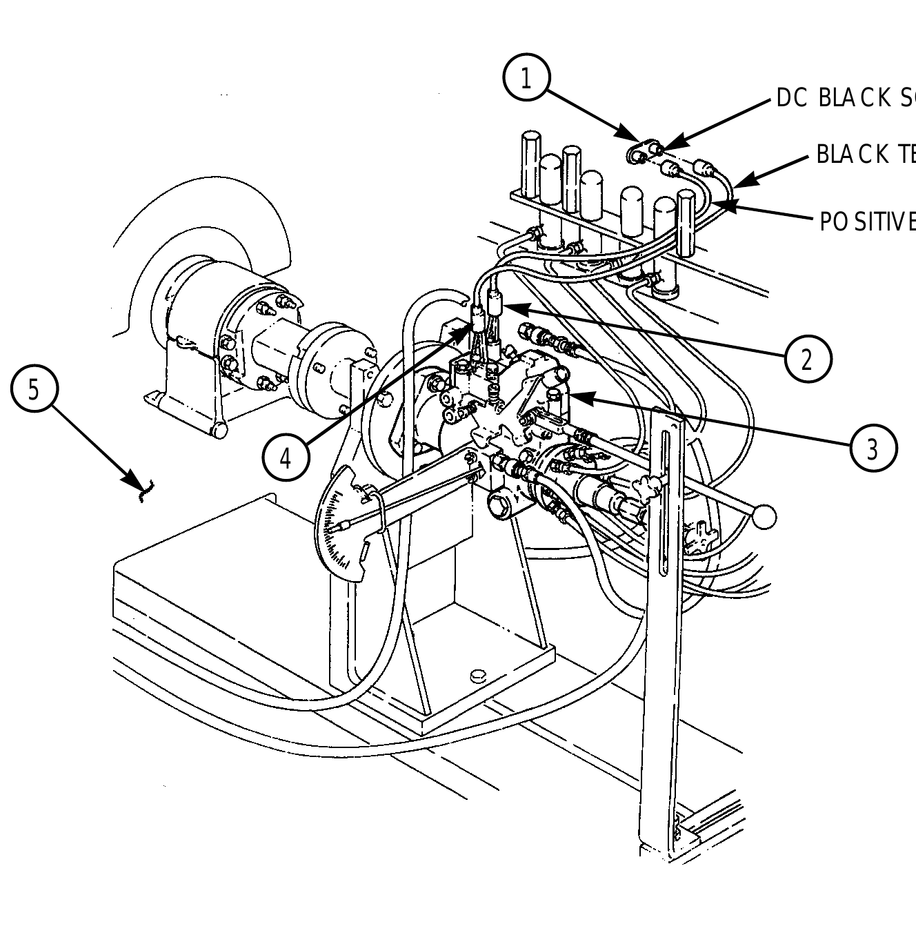
20. Connect positive red test lead to DC power supply socket marked (+) on test stand, and attach the alligator clip end of red test lead to the electric shutoff solenoid terminal (9) on fuel injection pump (2).
21. Connect black lead to DC black socket marked “P” on test stand and connect alligator clip end of black lead to ground terminal (10) on fuel injection pump (2).
22. After installation and hookup of the fuel injection pump has been completed, inspect pump, all hoses, and related hardware connections before beginning pump calibration. Review operation test procedures for the FTIS prior to calibrating the fuel injection pump.
7 6
ADVANCE INDICATOR 6 5 4
DB2831-5149) CALIBRATION USING FUEL INJECTION PUMP TEST STA N D (FTIS) MODEL A8022 (Cont’d)
AUXILIARY PRESSURE QUICK-CONNECT
TEST STAND FRONT PANEL
SCREW PLUG
QUICK-DISCONNECT
8 RUBBER HOSE ASSEMBLY
DC POWER SUPPLY DC BLACK SOCKET SOCKET BLACK TEST LEAD
POSITIVE RED TEST LEAD
TEST STAND 2
DB2831-5149) CALIBRATION USING FUEL INJECTION PUMP TEST STA N D (FTIS) MODEL A8022 (Cont’d)
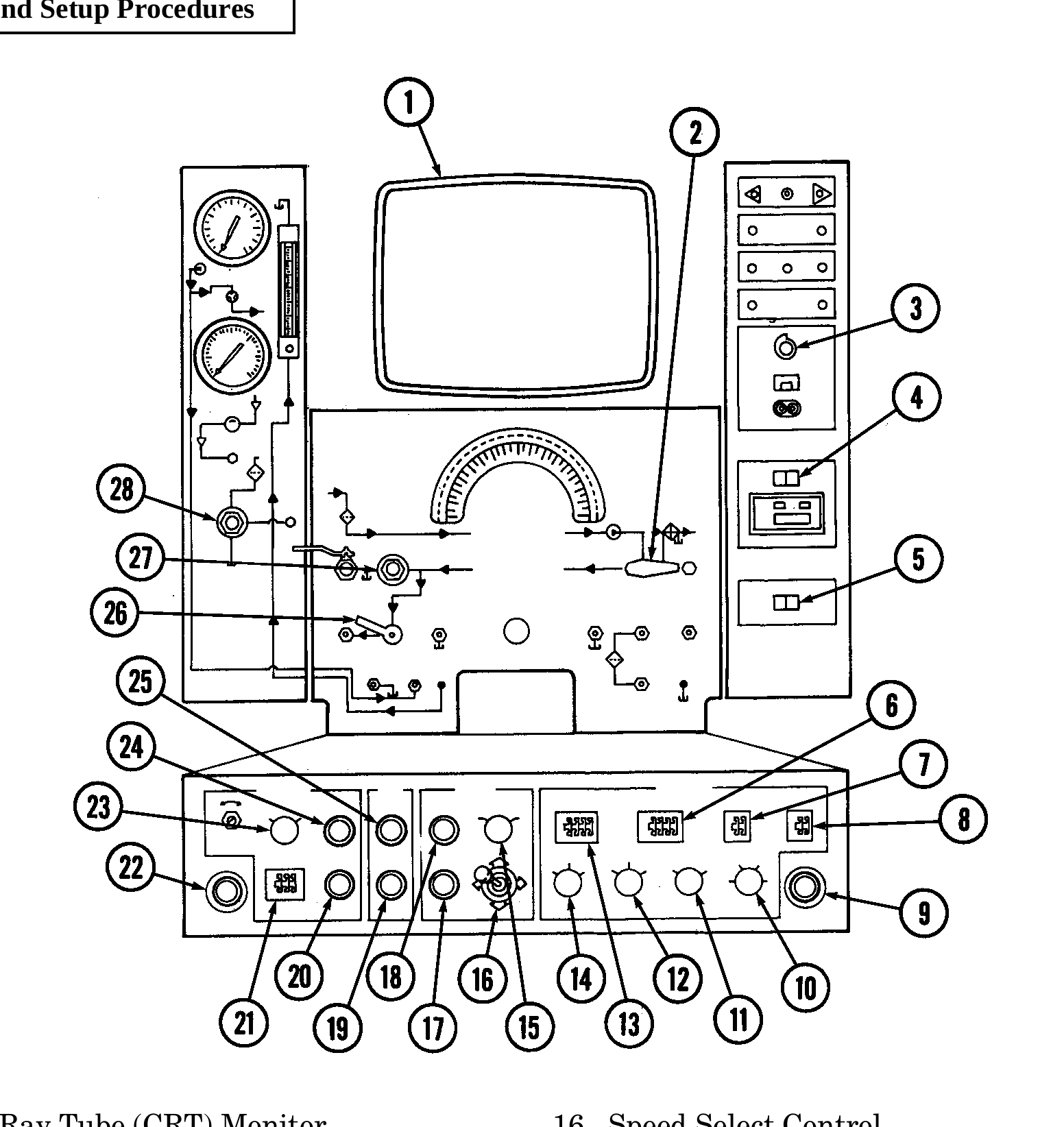
b. Test Stand Setup Procedures
1. Cathode Ray Tube (CRT) Monitor 16. Speed Select Control
2. Injection Pump/Auxiliary Selector 17. Main Drive Off
3. DC Supply Selector 18. Main Drive On
4. Printer Switch 19. Lube Oil System Off
5. Accumulator Switch 20. Calibration Fluid System Off Pushbutton
6. Low-Limit Thumbwheel 21. Nominal Temperature Thumbwheel
7. Outlet Number 22. Stop
8. Number of Outlets 23. Reservoir Bulkhead Selector
9. Stop 24. Calibration Fluid System On Pushbutton
10. Mode Selector 25. Lube Oil System On
11. Ratio Switch 26. Calibration Fluid System
12. Units Switch 27. Calibration Fluid Pressure
13. Hi-Limit Thumbwheel 28. Lube Pressure
14. Stroke
15. Pump Rotation Selector
DB2831-5149) CALIBRATION USING FUEL INJECTION PUMP TEST STA N D (FTIS) MODEL A8022 (Cont’d)
1. Set test stand in accordance with the following checklist and instructions in steps 2 through 25.
ITEM SETTING Bypass Valve Open Position Calibration Fluid System On Fluid Selector Valve Injection Pump Accumulator Switch Right Fluid Shutoff Valve On Mode Selector Auto Ratio Switch 1:2 Units Switch mm /stroke Stroke 50 Throttle WOT Number of Outlets 8 Outlet Number Between 1 and 8 Low-Limit Thumbwheel 10.0 Hi-Limit Thumbwheel Limit Thumbwheel 40.0 Pump Rotation Selector Counterclockwise Temperature Select Bulkhead Nominal Temperature Thumbwheel 44.7 Master Power Switch On DC Supply Selector 17.6 Volts Energize Electric Shutoff Solenoid (ESO) Lube Pressure 4.5 to 5.5 psi Lube Oil System Pushbutton On Main Drive Pushbutton On Printer Switch On Speed Select Control Increase/Decrease Control
2. Set fuel injection pump per calibration chart specifications and settings in para. 2-33, 2-34, or 2-35.
3. Secure throttle positioner arm in Wide Open Throttle (WOT) position.
4. Turn calibration fluid pressure regulator fully counterclockwise.
5. Press calibration fluid system on pushbutton.
6. Adjust calibration fluid pressure regulator knob clockwise until 4.5-5.5 psi (31-38 kPa) is indicated on the Cathode Ray Tube (CRT) monitor. Apply 17.6 volts by adjusting the variable DC voltage supply knob to energize the electric shutoff solenoid.
7. Turn on main drive system by pressing main drive on pushbutton and holding button depressed for a minimum of three seconds. Increase pump speed to approximately 150 rpm to prime transfer pump and bleed air from the high-pressure fuel line nuts at each test nozzle.
8. Increase pump speed to 1000 rpm. Ensure throttle lever is secured in WOT position. Run pump approximately 10 minutes to warm the calibration fluid to 110°-115°F (43.3°-46.1°C) and bleed all air from test stand and fuel pump. Observe transfer pump pressure reading on CRT monitor. It should be 70-76 psi (483-524 kPa).
DB2831-5149) CALIBRATION USING FUEL INJECTION PUMP TEST STA N D (FTIS) MODEL A8022 (Cont’d)
9. If transfer pump pressure does not read 70-76 psi (483-524 kPa), decrease pump speed to 0 rpm and turn off main drive and calibration fluid systems. Disconnect hose at hydraulic head fuel inlet port.
10. Adjust transfer pump pressure with 74-1137 5/32-in. Allen screw-driver (74-8032 adapter kit, slot 3, or equivalent) and reconnect hose. This pressure setting is critical. Repeat test and adjust until transfer pump pressure is within limits.
11. Check pump return flow. With pump speed at 1000 rpm WOT, pump return flow meter should read 225-375 cc/minute. Perform adjustment if necessary.
12. Reduce pump speed to 325 rpm. Move throttle lever 3 to LOW IDLE position and secure. The average flow reading on CRT monitor should be 10-18 mm /stroke. If flow is not correct, adjust low-idle screw or MIN-MAX governor setting to obtain proper flow.
13. With pump speed still at 325 rpm, and throttle lever secured in low-idle position, check/adjust variable DC voltage to 17.6 volts as follows: (a) Connect positive red test lead to cold-advance solenoid terminal. Housing pressure reading on CRT monitor should be 0-1 psi (0-7 kPa). (b) Disconnect positive red test lead from cold-advance solenoid terminal. Reduce variable DC voltage to 0 volts. Reconnect red test lead to shutoff solenoid terminal. Reduce pump speed to 200 rpm. (c) Slowly increase variable DC voltage and note voltage at which time the solenoid pulls in by listening for a clicking sound from the shutoff solenoid. (That indicates proper operation.) The shutoff solenoid should pull in with a maximum of 17.6 volts applied.
14. Reduce pump speed to 75 rpm. Move throttle lever to WOT position and secure. Average flow reading on CRT monitor must be a minimum of 28 mm3/stroke.
15. Increase pump speed to 200 rpm with throttle lever secured in WOT position. Average flow reading on CRT monitor must be a minimum of 47 mm /stroke. Disconnect positive red test lead from solenoid shutoff terminal. The average flow reading on CRT monitor must be 4 mm /stroke maximum. Reconnect positive red test lead to shutoff solenoid terminal.
16. Increase pump speed to 325 rpm. Move throttle lever to LOW IDLE position and secure. Average flow reading on CRT monitor should be 10-18 mm /stroke with a minimum of 1.5 degree cam movement on advance indicator. Connect positive red test lead to cold-advance solenoid terminal. Housing pressure reading on CRT monitor should be 0-1 psi (0-7 kPa) with a minimum of 2.75 degree cam movement on advance indicator. Reconnect positive red test lead to shutoff solenoid terminal.
17. Increase pump speed to 750 rpm. Adjust throttle lever to obtain average flow reading on CRT monitor of 21.5-23.5 mm /stroke and secure throttle lever. Advance indicator should have 2.25- 4.75 degree cam movement.
18. Increase pump speed to 1000 rpm. Move and secure throttle lever in WOT position. Average flow reading on CRT monitor should be 51.0-55.0 mm /stroke with 0.5-2.5 degree cam movement on advance indicator.
19. Increase pump speed to 1600 rpm and ensure throttle lever is secured in WOT position. There should be 4.25-7.25 degree cam movement on advance indicator. Move throttle lever to LOW IDLE position. There must be a maximum of 10.0 degree cam movement on advance indicator. Move and secure throttle lever in WOT position.
20. Increase pump speed to 1800 rpm and ensure throttle lever is secured in WOT position. Average flow reading on CRT monitor must be a minimum of 44.5 mm3/stroke.
21. Increase pump speed to 1950 rpm and ensure throttle lever is secured in WOT position. Average flow reading on CRT monitor must be a minimum of 42.5 mm3/stroke.
22. Increase pump speed to 2100 rpm and ensure throttle lever is secured in WOT position. Average flow reading on CRT monitor must be a maximum of 8 mm /stroke. Transfer pump pressure reading on CRT monitor must be a maximum of 135 psi (931 kPa).
DB2831-5149) CALIBRATION USING FUEL INJECTION PUMP TEST STA N D (FTIS) MODEL A8022 (Cont’d)
23. Reduce pump speed to 0 rpm and secure test stand. If pump met specifications, remove from test stand and mount in holding fixture. If pump did not meet specifications, repair as necessary and proceed to calibration instructions.
24. Using air timing gauge, check pump timing. Set timing to -0.75 to +1.25 degree.
25. Shut down test stand as follows: (a) Main drive pushbutton OFF. (b) Lube pushbutton OFF. (c) Calibration fluid pushbutton OFF. (d) DC selector OFF. (e) Master power switch OFF.
c. Removal of Fuel Injection Pump from Test Stand
1. Disconnect black test lead from DC black socket marked “P” on test stand (5), and remove alligator clip end of black test lead from ground terminal (4) on fuel injection pump (3).
2. Disconnect positive red test lead from DC power supply socket (1) marked (+) on test stand (5), and remove alligator clip end of red test lead from electric shutoff solenoid terminal (2) on fuel injection pump (3).
DC BLACK SOCKET
BLACK TEST LEAD
POSITIVE RED TEST LEAD
4 3
DB2831-5149) CALIBRATION USING FUEL INJECTION PUMP TEST STA N D (FTIS) MODEL A8022 (Cont’d)
3. Remove rubber hose assembly from quick-connect on advance indicator block and auxiliary pressure quick-connect on front panel of test stand (2).
4. Remove quick-connect from advance indicator block and install screw plug (1) into advance indicator block.
5. Remove two screws (7) and advance indicator from fuel injection pump (4), and install gasket (5) and timing cover (6) on fuel injection pump (4) with two screws (7).
6. Remove throttle arm positioner assembly from bedplate (8) and disconnect from throttle lever (3) on fuel injection pump (4).
7. Remove eight high-pressure delivery lines from discharge fittings (9) on fuel injection pump (4).
AUXILIARY PRESSURE QUICK-CONNECT
ADVANCE INDICATOR BLOCK RUBBER QUICK-CONNECT HOSE ASSEMBLY
DB2831-5149) CALIBRATION USING FUEL INJECTION PUMP TEST STA N D (FTIS) MODEL A8022 (Cont’d)
3 4
THROTTLE ARM POSITIONER ASSEMBLY ADVANCE INDICATOR
7 5
HIGH-PRESSURE DELIVERY LINE
DB2831-5149) CALIBRATION USING FUEL INJECTION PUMP TEST STA N D (FTIS) MODEL A8022 (Cont’d)
8. Disconnect tubing from male pipe fitting on fuel injection pump (1) and from calibration fluid push- on connector (3) on front panel of test stand (5).
9. Remove male pipe fitting from fuel injection pump (1).
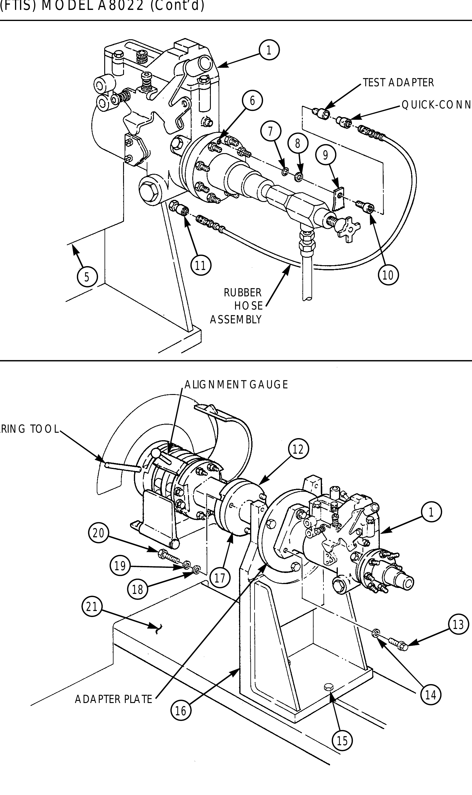
10. Disconnect rubber hose assembly from quick-connect plug on test adapter and from auxiliary pressure quick-connect (11) on front panel of test stand (5).
11. Remove quick-connect plug from test adapter.
12. Remove test adapter, tab (9), washer (8), and O-ring (7) from transfer test port (6) of fuel injection pump (1).
13. Install O-ring (7), washer (8), tab (9), and screw (10) in transfer test port (6) of fuel injection pump (1).
14. Disconnect hose assembly from connector and calibration fluid supply quick-connect (4) on front panel of test stand (5).
15. Remove test adapter and connector from fuel inlet port (2) of fuel injection pump (1).
16. Remove three 3/8-16x1 hex-head capscrews (20), 3/8-in. lockwashers (19), and 3/8-in. washers (18) from slots and mounting holes on test stand drive coupling (12) and pump-mounted drive hub (17).
17. Loosen two 3/8-16x1 hex-head capscrews (15) from flange mounting bracket (16) and bedplate (21).
18. Remove flange mounting bracket (16) and fuel injection pump (1) from test stand drive coupling (12) and remove alignment gauge and barring tool.
19. Remove three 5/16-18x1 hex-head capscrews (13), 5/16-in. washers (14), and fuel injection pump (1) from adapter plate.
TUBING
MALE PIPE FITTING
TEST ADAPTER
CONNECTOR
HOSE ASSEMBLY
DB2831-5149) CALIBRATION USING FUEL INJECTION PUMP TEST STA N D (FTIS) MODEL A8022 (Cont’d)
TEST ADAPTER 6 QUICK-CONNECT PLUG
5 10 RUBBER HOSE ASSEMBLY
ALIGNMENT GAUGE
BARRING TOOL
ADAPTER PLATE 14
Change 1 2-140.25/(2-140.26 blank)