2-13.1. Engine Replacement In Shipping/Storage Container
TM 9-2815-237-34 · Chapter 2 — Engine Maintenance
AINER This task covers:
a. Removal b. Installation
INITIAL SETUP:
  Tools                                                 Manual References
   General mechanic’s tool kit:                          TM 9-2815-237-34P
    automotive (Appendix E, Item 1)                     Personnel Required
  Special Tools                                          One mechanic
   Engine lifting sling (Appendix E, Item 3)             One assistant
  Materials/Parts                                       General Safety Instructions
   Eight lockwashers (Appendix D, Item 26.1)             Direct personnel to stand clear during hoisting
                                                         operation.

a. Removal

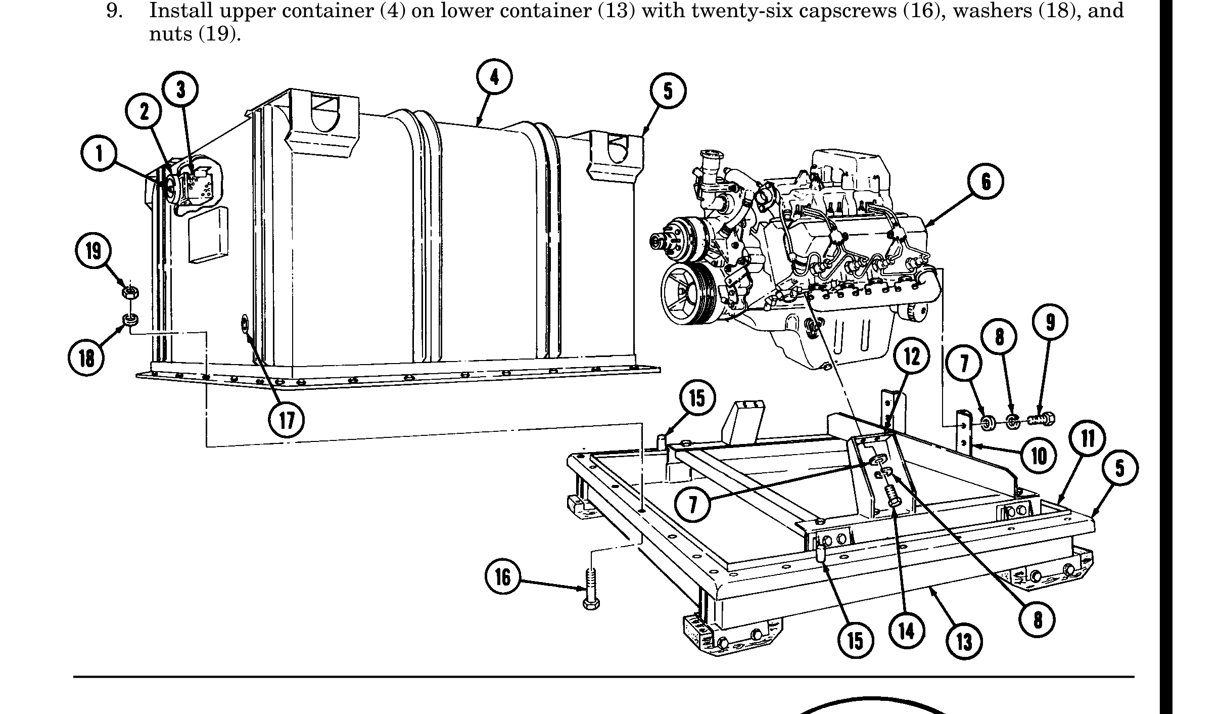
 1.   If engine container (5) is closed and sealed, press air-release button (1) located at center of breather
      valve (2) before opening engine container (5).
 2.   Remove twenty-six nuts (19), washers (18), capscrews (16), and upper container (4) from lower
      container (13).
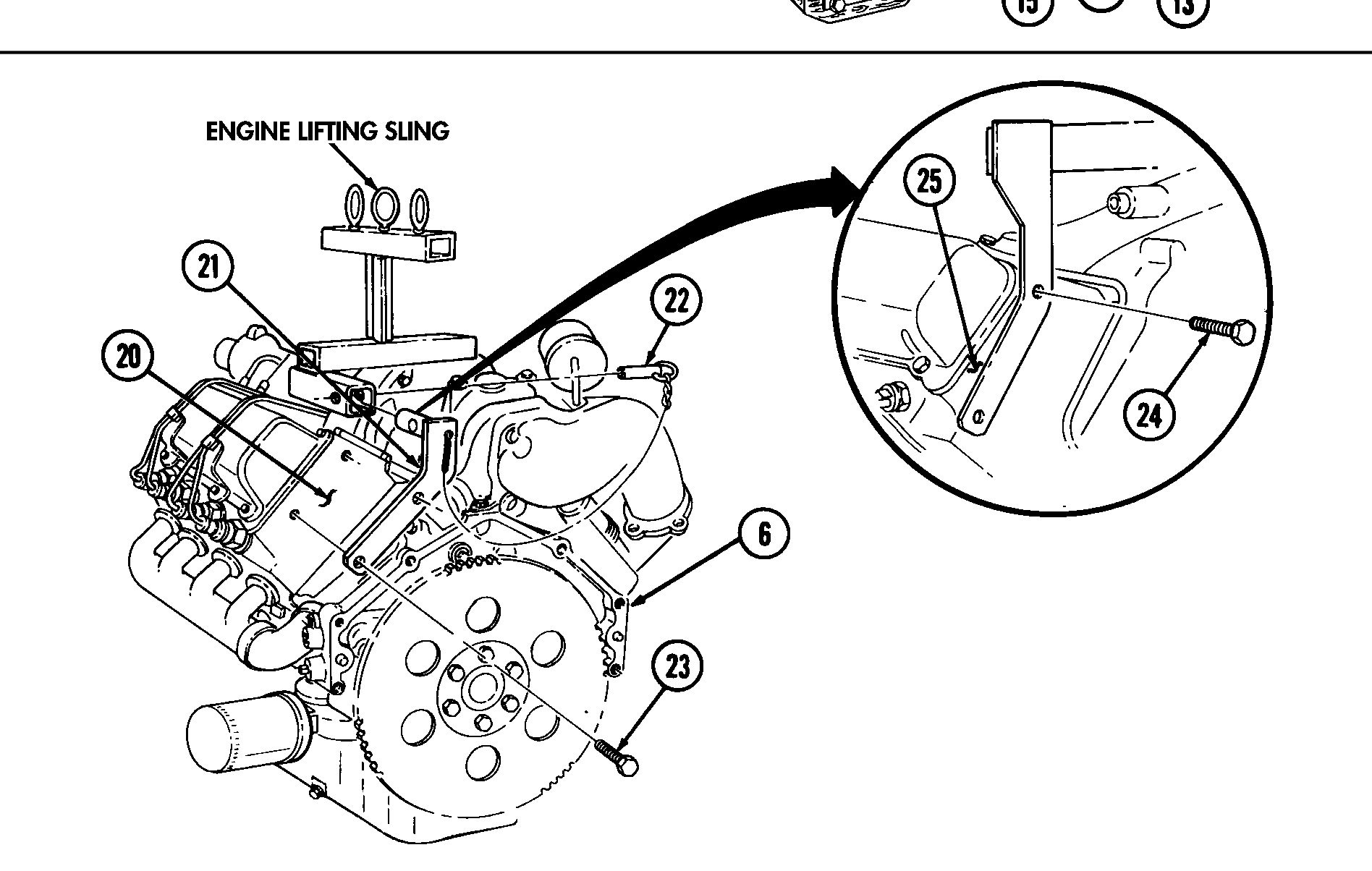
 3.   Position engine lifting sling on engine assembly (6) and install sling on right cylinder head (25) with
      two capscrews (24).
 4.   Install sling bracket (21) to engine lifting sling with pin (22) and on left cylinder head (20) with two
      capscrews (23). Tighten capscrews (23).
 5.   Remove four capscrews (14), lockwashers (8), and washers (7) from two engine mounts (12). Discard
      lockwashers (8).
 6.   Remove four capscrews (9), lockwashers (8), and washers (7) from two rear engine mounts (10).
      Discard lockwashers (8).
                                               WARNING
                Direct personnel to stand clear during hoisting operation. Failure to do this
                may cause injury to personnel.
 7.   Attach hoist to engine lifting sling and remove engine assembly (6) from lower container (13).
 8.   Position engine on repair stand (para. 2-14).

b. Installation

 1.   Install engine assembly (6) in lower container (13).
 2.   Install engine assembly (6) on two rear engine mounts (10) with four washers (7),
      lockwashers (8), and capscrews (9).
 3.   Install engine assembly (6) on two engine mounts (12) with four washers (7), lockwashers (8), and
      capscrews (14).
 4.   Remove pin (22) from sling bracket (21).
 5.   Remove two capscrews (24) and lifting sling from right cylinder head (25).
 6.   Remove two capscrews (23) and sling bracket (21) from left cylinder head (20).
 7.   Visually check humidity indicator (17) for discolorization. If indicator (17) is dark purple, replace
      desiccant (3).
TM page Change 1 2-7
NOTE Ensure gasket is seated properly.
8. Using alignment pins (15), position upper container (4) on gasket (11) and lower container (13).
9. Install upper container (4) on lower container (13) with twenty-six capscrews (16), washers (18), and nuts (19).
TM page 2-8 Change 1